Method In A Production System For Limiting Peak Power

a production system and peak power technology, applied in forging presses, manufacturing tools, forging/pressing/hammering apparatuses, etc., can solve the problems of low production rate, long cycle time, and low speed of complete operation, and achieve the effect of short cycle time, increased flexibility of production cycle, and sufficient mounting accuracy and rigidity

Active Publication Date: 2011-09-29
ABB (SCHWEIZ) AG
View PDF9 Cites 11 Cited by
  • Summary
  • Abstract
  • Description
  • Claims
  • Application Information

AI Technical Summary

Benefits of technology

[0024]According to another embodiment of the present invention a method is described for operating a production system comprising at least one mechanical press driven at least in part by a flywheel powered by a first motor, said system further comprising a second motor, which is a servo motor, the method comprising controlling the power of said first motor powering the flywheel dependent on a function of at least one said second motor, the servo motor, and controlling said first motor, the motor of the flywheel, to limit the total peak power, both positive and negative, of said first motor and said second motor to a value which is equal to or lower than the peak power of said second motor, the servo motor.
[0047]Tests with prototypes have been carried out using an estimated power setpoint. Since the real power has some delay compared to the setpoint, this means that the power of the flywheel motor may be changed in time. However, if the actual power (i.e. not the setpoint but the real value) was used, control of the flywheel motor would have to be instantaneous in order to avoid spikes in the total power. Thus use of a setpoint for power or a function of a setpoint for power of the second motor, the servo motor, provides the further advantage of providing a control mode over one or multiple first motors, flywheel motors which limits total peak power for parts of the system and which, in practice, places fewer demands on control systems running the production system.
[0049]The Press Motor Upgrade Kit described therein is a unit which is mounted on the press in one part. It is fixed to the top or other structural part of the press crown, with sufficient mounting accuracy and rigidity. On the baseplate or structure of the unit is mounted the (servo) motor or motors. Through a coupling this motor is connected to gear wheels of the mechanical press, which gears will typically reduce the speed of the motor to a lower speed of an existing gear in the press crown. This connection will then allow the upgrade motor to move the press gears at variable speed, both in positive and negative direction and up to a higher speed (eg. 50% higher) when not stamping than the maximum stamping speed the mechanical press drive was originally designed for. Another advantage is the increased flexibility of production cycle made possible. For example, the hybrid servo technology described here allows pressing at lower speed while maintaining cycle time, or alternatively pressing at an identical speed but with shorter cycle time, or a mix of these two.
[0050]The ability to reduce peak power by a factor two is very advantageous, both for new installations and retrofits. For a new installation, cost of components such as the rectifier, the cabling and protection equipment will be significantly lower. For a retrofit, the power limitation allows an improvement in the performance of an existing installation or production system without the technical challenges financial cost of having to upgrade the factory electrical power supply. In both the new and the retrofit cases, a reduced cost for electrical power is provided by peak power limitation when the power utility is billing for peak power, in which case the normal expected cost for electrical power is reduced compared to what would normally be expected with motors running at the peak of their rated power.

Problems solved by technology

Thus, if pressing has to be done at a low speed (for quality or other technical reasons), the complete operation will occur at low speed.
This results in a long cycle time, and therefore, a low production rate.
However, this option has high risks for both press manufacturers and their customers: the design will be new and thus unproven, and most often manufacturers and customers have, as yet, few or no clear specifications for how such a design should perform.
As a result, different manufacturers will likely offer very different servo press designs, some slower than existing mechanical presses, some with extremely high power requirements, and in general with very different performances which may be unpredictable over a long service life.
However, the servo press requires a large motor and power converter (approx. five times larger than the fully mechanical press).
In a new installation a larger power supply can be so dimensioned from the start, however, in both cases an increased cost is to be expected.

Method used


Image

  • Method In A Production System For Limiting Peak Power
  • Method In A Production System For Limiting Peak Power
  • Method In A Production System For Limiting Peak Power

Examples


Embodiment Construction

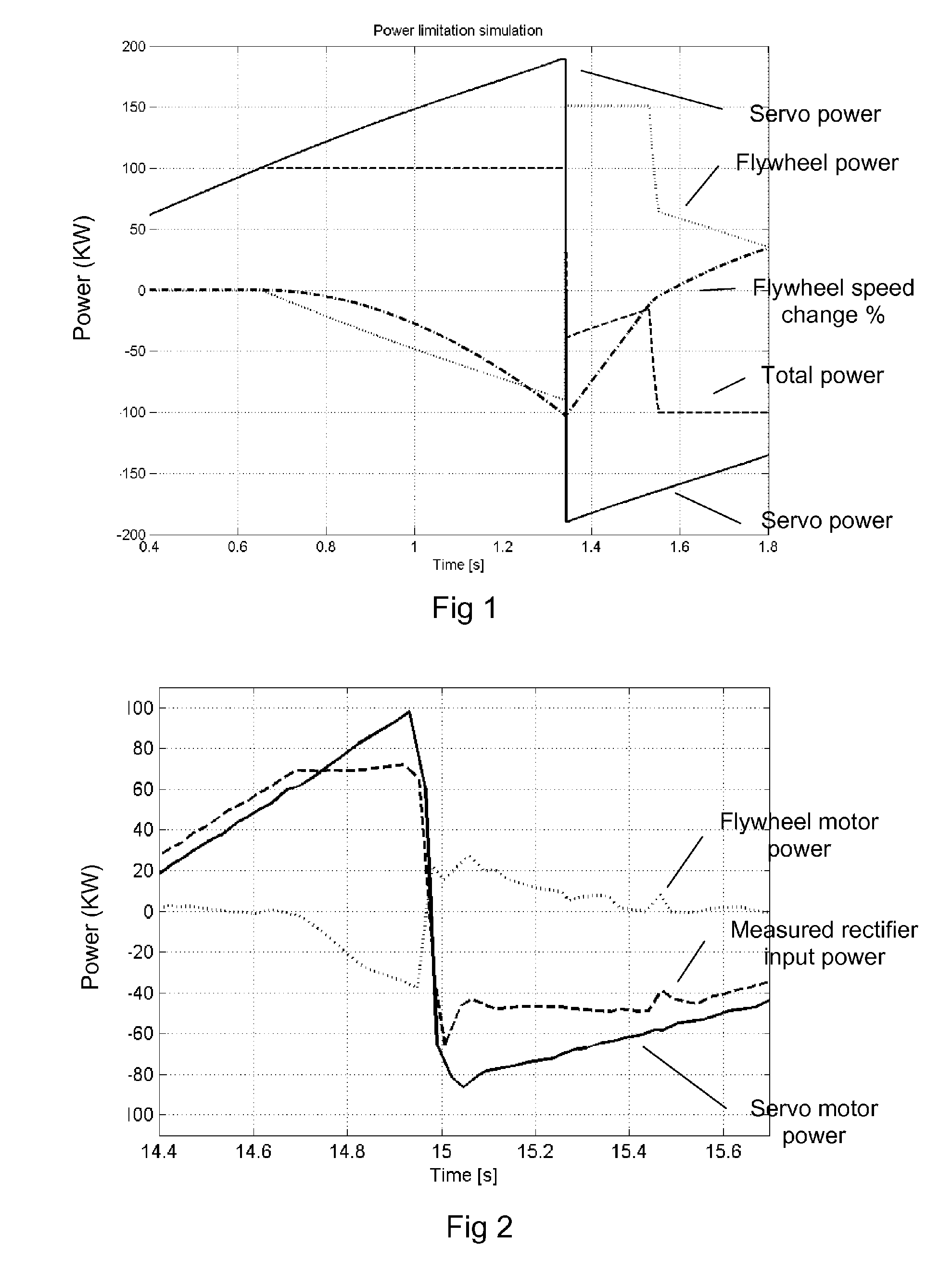
[0060]FIG. 1 is a diagram showing measured values against time (in seconds) for a simulation of peak power limiting by controlling a flywheel motor dependent on power of a servo motor. The curves show values for servo motor power, flywheel motor power, flywheel speed changes in %, and total power which is the combined total power consumption of both motors.

[0061]In this simulation torque control has been assumed ideal and instantaneous. An example simulation is shown in FIG. 1. Here, the total power limit had been set to 100 kW. As soon as servo power increases above this value, flywheel motor power becomes negative, keeping the total at 100 kW. When the sign of the servo power changes, the flywheel speed controller first brings flywheel speed back to close to its desired value. Then, the power limitation continues to ensure that negative total power is limited to −100 kW. In this simulation, flywheel speed drops by only 1%.

[0062]FIG. 2 is a diagram showing measured values against t...


PUM

PropertyMeasurementUnit
total poweraaaaaaaaaa
poweraaaaaaaaaa
poweraaaaaaaaaa

Abstract

A production system has at least one mechanical press driven at least in part by a flywheel powered by a first motor. The system further includes a second motor which is a servo motor. The power of the first motor powering the flywheel is arranged controlled by a control unit dependent on a function of the power of at least one second motor, the servo motor. In this way, the peak power of at least the first and the second motor may be limited. A method for operating the system and a computer program are also contemplated.

Description

CROSS-REFERENCE TO RELATED APPLICATIONS[0001]The present application is a continuation of pending International patent application PCT / EP2008 / 066946 filed on Dec. 5, 2008 which designates the United States, and the content of which is incorporated herein by reference.FIELD OF THE INVENTION[0002]The invention concerns a method for operating a production system for forming parts or semi-finished products comprising at least one mechanical press arranged with an electric motor driving a high inertia device such as a flywheel. In particular the invention is concerned with a method of limiting peak power consumption in such a production system. Advantageous configurations for production systems comprising any of mechanical presses, hybrid presses and / or servo presses are also described.BACKGROUND OF THE INVENTION[0003]Mechanical presses are commonly used to form industrial products such as automobile parts which are stamped or pressed from steel blanks or workpieces. Today's large mechan...

Claims


Application Information

Patent Timeline
Patent Type & Authority Applications(United States)
IPC IPC(8): B30B15/14B30B1/00
CPCB30B1/266B30B15/26B30B15/148Y02P70/10B30B1/26B30B15/14
Inventor BOSGA, SJOERD
Owner ABB (SCHWEIZ) AG
Why Eureka
Try Eureka