
LED driver and lighting application for wattage control

a technology of wattage control and led driver, which is applied in the direction of electrical equipment, electrical variable regulation, instruments, etc., can solve the problems of difficult and time-consuming, difficult to manage fixture power requirements, and difficulty in subsequent certification of electrical installations, etc., to achieve convenient setting or configuring the maximum power consumption, reduce the maximum wattage of the lighting grid, and reduce the effect of power consumption

Active Publication Date: 2012-07-12
ELDOLAB HLDG
View PDF9 Cites 10 Cited by
  • Summary
  • Abstract
  • Description
  • Claims
  • Application Information

AI Technical Summary

Benefits of technology

[0005]It would be desirable to provide an LED driver for powering an LED fixture that enables an improved or more efficient way of meeting various building code regulations or enables an easier way of determining an installed wattage of a plurality of lighting devices. Further, it would also be desirable to ensure that, once an installation such as an LED based lighting application has been certified or approved, the maximum power consumption drawn or lighting power density cannot be tampered with or altered unless the electrical driver is removed and replaced risking non compliance to the energy code.

Problems solved by technology

Such an inspection and subsequent certification of an electrical installation may thus be difficult and time-consuming.
Further, from a manufacturer's point of view, it is often cumbersome to design or stock inventory to an electrical installation, e.g. comprising a plurality of lighting applications that makes optimal use of the allowable power consumption.
Typically, due to such differences in building designs it is often difficult to manage fixture power requirements and it would require mixing and matching of devices of different wattage in order to comply with a building code requirement, or Lighting Power Densities.
This could be cumbersome, both with respect to design effort, maintenance and support or turnover stock.

Method used


Image

  • LED driver and lighting application for wattage control
  • LED driver and lighting application for wattage control

Examples


Embodiment Construction

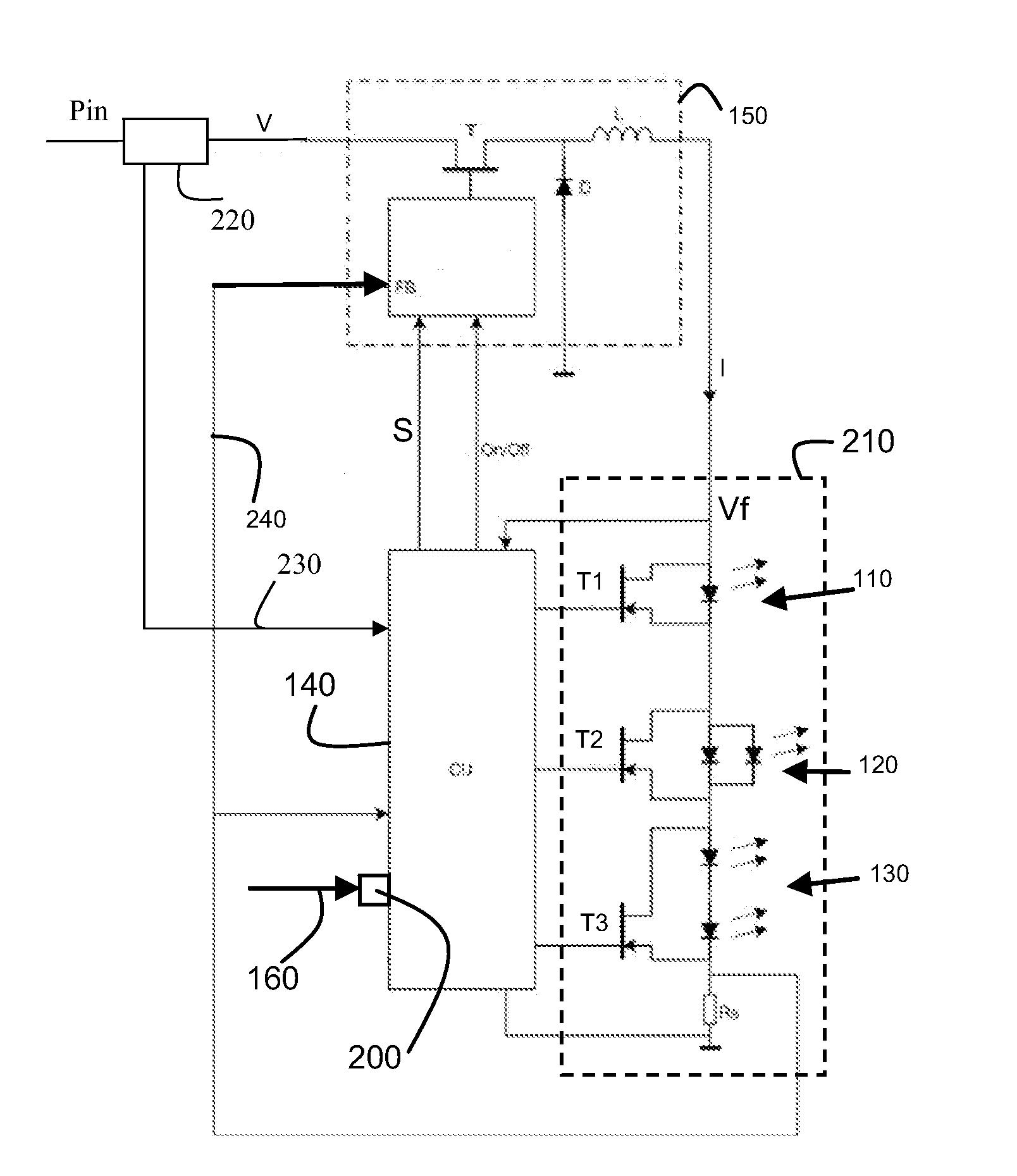
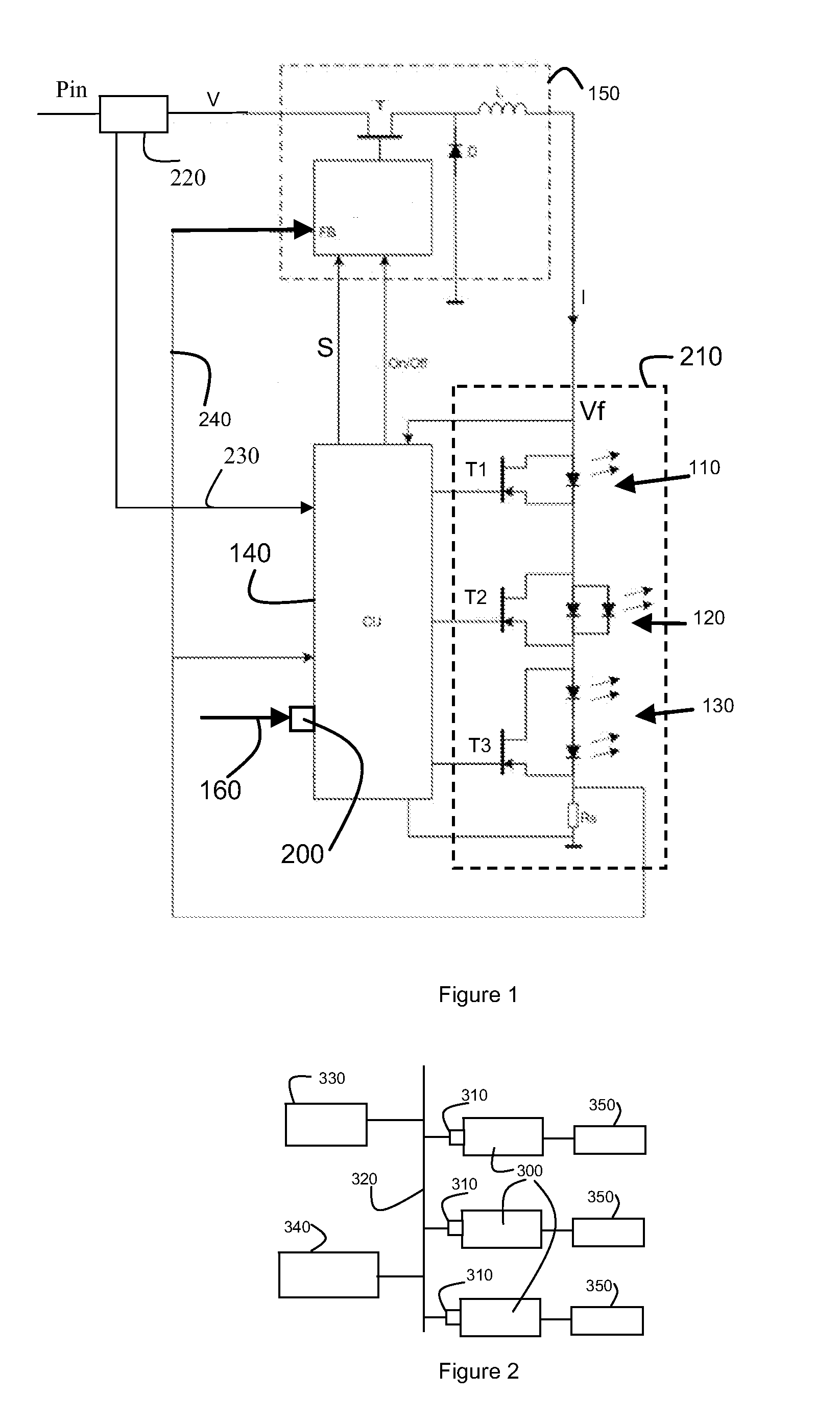
[0051]FIG. 1 depicts an LED driver according to an embodiment of the invention, the LED driver comprising a power converter 150 and a control unit 140. As shown, the power converter 150 is arranged to power an LED fixture 210 comprising three LED units (110,120,130), each comprising one or more LEDs. In general, when referring to an LED fixture, this is understood as comprising at least one LED. In accordance with the invention, the control unit 140 is arranged to control an output characteristic (e.g. the current I as provided to the LED fixture 210). This is schematically depicted by the control signal S as shown. The control signal S can e.g. be applied by the power converter to control the switching element T of the converter thereby controlling the current I as supplied by the power converter to the LED fixture. As such, the control signal can e.g. comprise a current set-point for the power converter whereby the power converter controls the duty cycle of the switching element T...


PUM


Abstract

An LED driver for powering an LED fixture is described, the LED driver comprising:an input terminal for receiving an input power;a power converter arranged toreceive an input power at an input terminal of LED driver;convert the input power to an output power for powering the LED fixturea sensing device for sensing the input power received by the power converter;a control unit arranged to control an output characteristic of the power converter;a configuration terminal connected to the control unit;the control unit further being arranged to:receive, from the sensing device, a signal representing the sensed input power;receive, via the configuration terminal, a configuration signal representing a maximum wattage for the LED driver; andcontrol the output characteristic of the power converter such that the input power as sensed does not exceed the maximum wattage.

Description

FIELD OF THE INVENTION[0001]The invention relates to the field of power consumption management of electrical devices, in particular lighting applicationsBACKGROUND OF THE INVENTION[0002]At present, electrical installations of buildings, in particular lighting applications installed, are subjected to power limitations, e.g. indicated as a maximum power consumption per square feet, or Lighting Power Densities, which are represented as Watts per Sq. Feet which are part of building codes that need to be met prior to the use of the electrical installation. In practice, an Authority Having Jurisdiction (AHJ) or building inspector would verify if the total installed wattage of an electrical installation is compliant or acceptable, as required by building code restrictions, or requirements with respect to power consumption. Such a check would in general require verifying the wattage of each device of the electrical installation, e.g. based on the labeling on the devices, adding the total in...

Claims


Application Information

Patent Timeline
Patent Type & Authority Applications(United States)
IPC IPC(8): H05B37/02H05B44/00
CPCH05B33/083H05B33/0815H02M3/156H05B45/48H05B45/10H05B47/175H05B45/375H05B45/3725H05B45/38G01R21/133G01R21/06
Inventor SAES, MARC
Owner ELDOLAB HLDG
Learn More