
Directed magnetic field coil design

a magnetic field coil and coil design technology, applied in the direction of transformers/inductances, magnetic cores of inductances, instruments, etc., can solve the problems of large power drain on batteries, adversely affecting battery operation, heating mechanical devices, etc., and achieve the effect of reducing the magnetic field

Active Publication Date: 2019-01-24
INTEGRATED DEVICE TECH INC
View PDF0 Cites 7 Cited by
  • Summary
  • Abstract
  • Description
  • Claims
  • Application Information

AI Technical Summary

Benefits of technology

The present invention provides a coil arrangement that includes one or more coils positioned to reduce magnetic field levels in areas surrounding the arrangement. The coils have a bent or flattened shape to direct the magnetic flux and minimize interference. The invention also includes a method for simulating field strengths and determining the optimal placement of multiple coils. The technical effect is an improved design for coil configurations that provide optimized magnetic field levels in specific areas, reducing interference and improving performance.

Problems solved by technology

However, in many of these applications, operation of the coils can cause heating of the mobile device, can provide a large power drain on the battery, and may adversely affect operation of the battery.
In particular, magnetic field lines that do not contribute to the functionality of the coil can cause heating of the mechanical device and may adversely affect the battery of the device itself.
Further, these magnetic field lines that are not directly involved in the functionality of the coil represent inefficiencies in operation.

Method used


Image

  • Directed magnetic field coil design
  • Directed magnetic field coil design
  • Directed magnetic field coil design

Examples


Embodiment Construction

[0029]In the following description, specific details are set forth describing some embodiments of the present invention. It will be apparent, however, to one skilled in the art that some embodiments may be practiced without some or all of these specific details. The specific embodiments disclosed herein are meant to be illustrative but not limiting. One skilled in the art may realize other elements that, although not specifically described here, are within the scope and the spirit of this disclosure.

[0030]This description and the accompanying drawings that illustrate inventive aspects and embodiments should not be taken as limiting—the claims define the protected invention. Various changes may be made without departing from the spirit and scope of this description and the claims. In some instances, well-known structures and techniques have not been shown or described in detail in order not to obscure the invention.

[0031]Elements and their associated aspects that are described in det...


PUM

PropertyMeasurementUnit
heightaaaaaaaaaa
heightaaaaaaaaaa
heightaaaaaaaaaa

Abstract

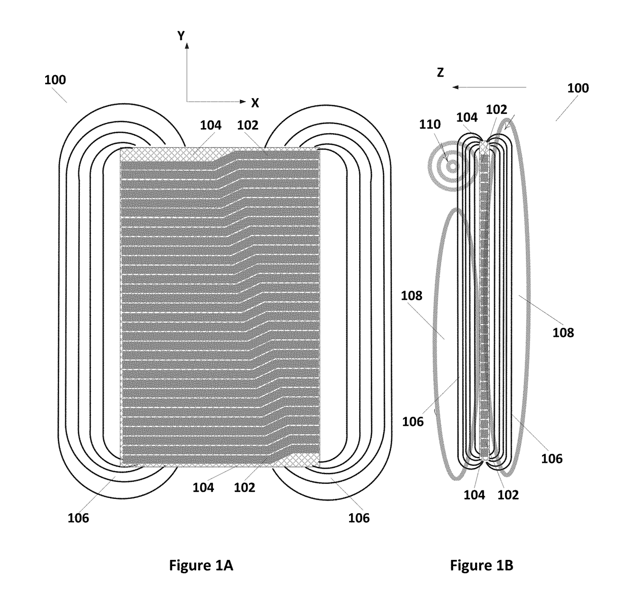
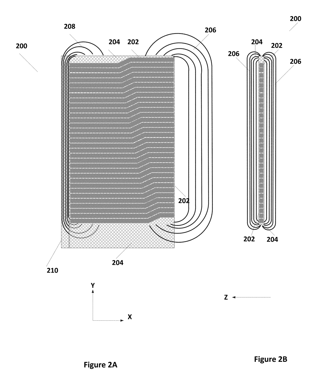
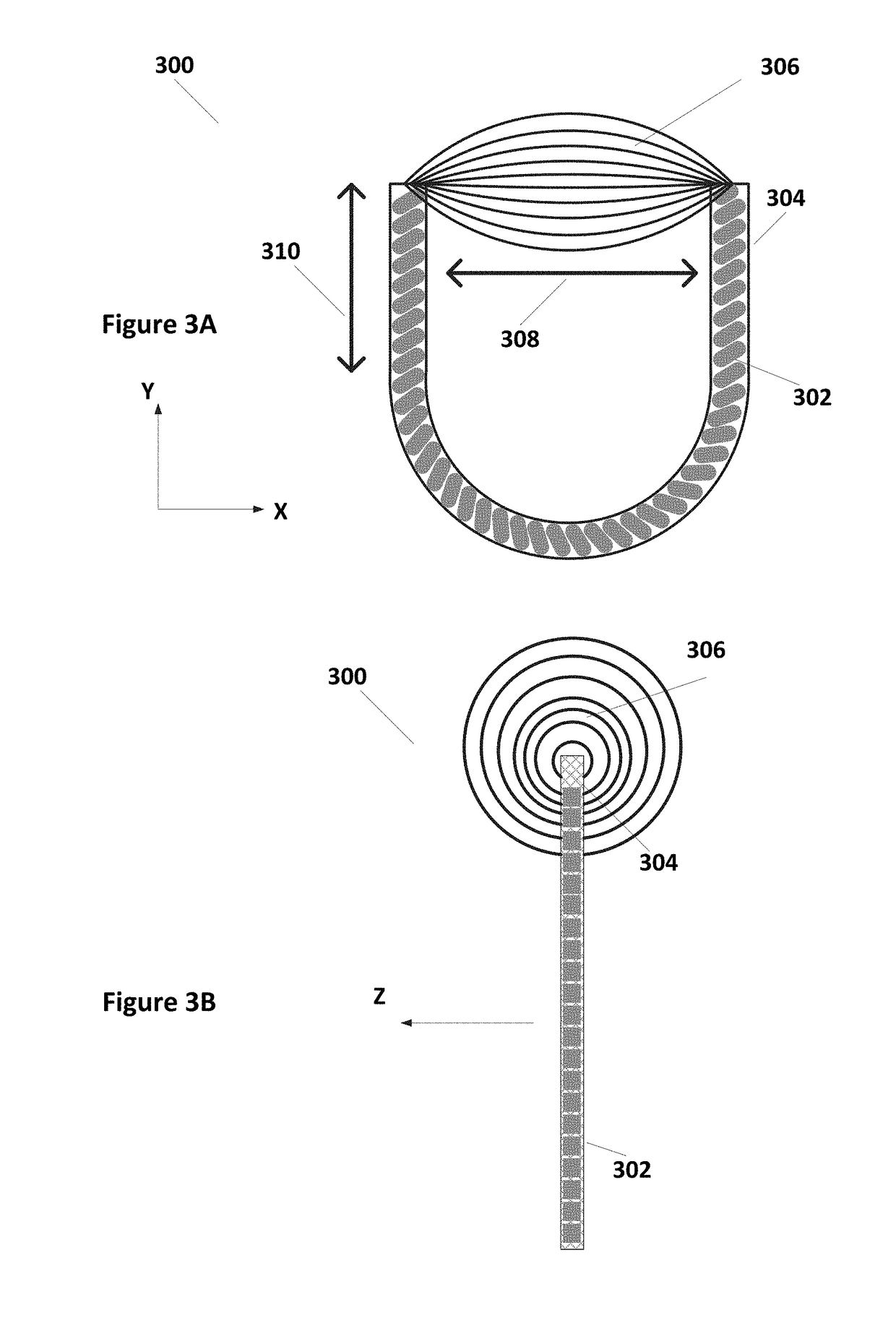
In accordance with aspects of the present invention, a coil arrangement is presented. A coil arrangement according to some embodiments includes at least one coil positioned to provide a magnetic field in a first area and configured to reduce the magnetic field in a second area outside of the first area. In some embodiments, the at least one coil includes a bent solenoid oriented in the X-Y plane, the bent solenoid localizing magnetic field flux at ends of the bent solenoid. In some embodiments, the bent solenoid can include end caps to further direct the magnetic flux. In some embodiments, the at least one coil includes a flattened solenoid with end caps to direct the magnetic flux. In some embodiments, the coil arrangement is a configuration of multiple coils.

Description

RELATED APPLICATIONS[0001]The present disclosure claims the benefit of U.S. Provisional Application No. 62 / 559,477, filed Sep. 15, 2017, and is a continuation-in-part of U.S. application Ser. No. 16 / 012,682, filed Jun. 19, 2018, which claims the benefit of U.S. Provisional Application No. 62 / 522,026, filed Jun. 19, 2017, all of which are herein incorporated by reference in their entirety.TECHNICAL FIELD[0002]Embodiments of the present invention are related field coil design and, in particular, to magnetic field coil design for power transfer and for communications.DISCUSSION OF RELATED ART[0003]Magnetic field coils are used throughout mobile devices. These uses include, for example, wireless power transfer and wireless communications such as, for example, magnetic secured transmission. In some applications, a single coil installation has multiple functionalities. In other applications, a single wireless device may include multiple coils, each performing different functionalities.[00...

Claims


Application Information

Patent Timeline
Patent Type & Authority Applications(United States)
IPC IPC(8): G06F17/50H01F38/14H02J50/10H04B5/00
CPCG06F17/5009H01F38/14H02J50/10H04B5/0087H04B5/0037G06F2217/78H01F27/255G06F2111/10G06F30/20H01F27/36H04B5/72H04B5/79H04B5/263G06F2119/06H01F2038/143H01F27/24
Inventor MEHAS, GUSTAVOQI, TAO
Owner INTEGRATED DEVICE TECH INC
Learn More