Method for optimizing aluminium electrolysis slot field

An aluminum electrolytic cell and an optimization method technology, applied in the field of optimizing the magnetic field of an aluminum electrolytic cell, can solve the problems of reduced current efficiency, enhanced magnetic field, and easy damage of the cell body, and achieve the effect of reducing the magnetic field

Active Publication Date: 2008-09-03
GUIZHOU BRANCH CHINA ALUMINUM IND
View PDF2 Cites 7 Cited by
  • Summary
  • Abstract
  • Description
  • Claims
  • Application Information

AI Technical Summary

Problems solved by technology

[0002] With the enlargement of the aluminum electrolytic cell, the stability of the magnetic fluid is becoming more and more important in the production of the electrolytic cell. Since the structural characteristics of the electrolytic cell entity determine the inhomogeneity of the magnetic field distribution of the electrolytic cell, the current busbar configuration method is in The magnetic field generated by the body of the electrolytic cell and the upper busbar is based on the peak-shaving and valley-filling of the busbar at the bottom of the tank to make the magnetic field of the aluminum liquid layer tend to be as uniform as possible. In fact, only the maximum and average values ​​of the magnetic field can be reduced. Due to the inhomogeneity of the magnetic field and the compensation bus current on the way to compensate one position, it will inevitably strengthen the magnetic field at other positions, which will cause the magnetic field of the aluminum liquid layer to rise and fall one after another, restraining each other, and finally cannot be reduced to the ideal situation.
The side effect of the instability of the ferrofluid in the electrolytic cell is more obvious in the large electrolytic cell. The electromagnetic force is enhanced and the movement of the aluminum liquid is accelerated, which will lead to unstable production, increased power consumption, reduced current efficiency, and easy damage to the cell.

Method used


Image

  • Method for optimizing aluminium electrolysis slot field
  • Method for optimizing aluminium electrolysis slot field
  • Method for optimizing aluminium electrolysis slot field

Examples


Embodiment Construction

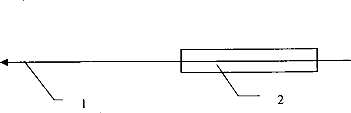
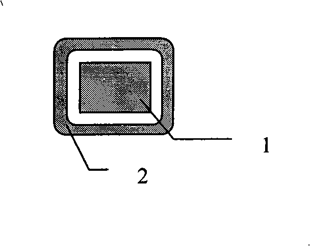
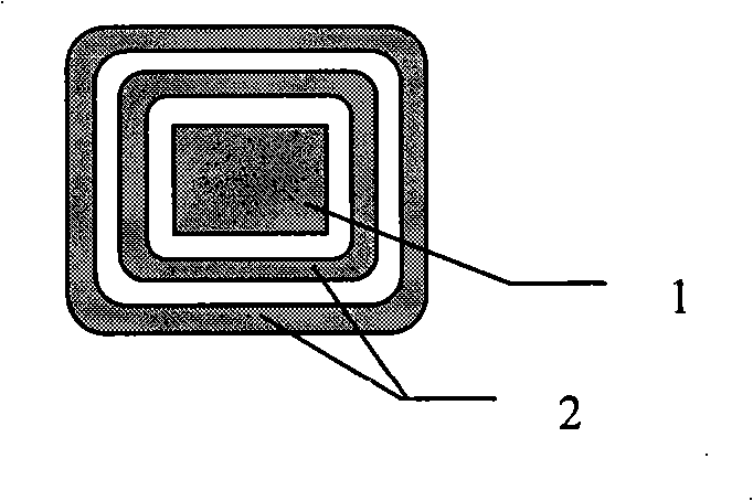
[0015] The vertical magnetic field Bz of the aluminum liquid layer in the tank generally has a maximum value at the four corners, and is close to anti-symmetry about the X and Y axes, as shown in Figure 4. Among them, the schematic diagram of the direction of the vertical magnetic field Bz of the aluminum liquid layer at 1, when the compensation bus 2 When the end of the electrolyzer is from the power-in A side to the power-out B side, the direction of the vertical magnetic field generated by the compensation busbar is positive, which will cause that when the busbar compensation B side reduces its negative Bz, it will increase the A side at the same time The positive maximum value of the corner, in order to reduce the impact on the right side of the A surface, we add a shield 3 to the corresponding part of the busbar, as shown in Figure 4, the shield is made according to the content of the invention, according to the needs It is determined that it is a single-layer shielding co...


PUM


Abstract

The invention provides a method for optimizing the in-cell magnetic field of aluminum electrolysis cell, relating to a magnetic field optimizing method for configuring bus of aluminum electrolysis cell. The method is characterized in that: on the way that the compensation bus goes to the object position, a ferromagnetic shielding cover is sheathed on a section where the bus has negative effect to the in-cell magnetic field in order to reduce side effect of the bus. The method effectively overcomes the drawback of the traditional compensation bus configuration by sheathing the shielding cover around part of the compensation bus located at the bottom of the electrolysis cell, thus, the compensation bus has little negative effect on the other magnetic field on the way for reducing the magnetic field of the object position, so that the magnetic field of the electrolysis cell can be easily reduced, especially applicable for the bus configuration design of large aluminum electrolysis cell with the advantages of being stable, high efficiency, long life.

Description

technical field [0001] A method for optimizing a magnetic field in an aluminum electrolytic cell relates to a magnetic field optimization method for bus bar configuration in an aluminum electrolytic cell. Background technique [0002] With the enlargement of the aluminum electrolytic cell, the stability of the magnetic fluid is becoming more and more important in the production of the electrolytic cell. Since the structural characteristics of the electrolytic cell entity determine the inhomogeneity of the magnetic field distribution of the electrolytic cell, the current busbar configuration method is in The magnetic field generated by the body of the electrolytic cell and the upper busbar is based on the peak-shaving and valley-filling of the busbar at the bottom of the tank to make the magnetic field of the aluminum liquid layer tend to be as uniform as possible. In fact, only the maximum and average values ​​of the magnetic field can be reduced. Due to the inhomogeneity of...

Claims


Application Information

Patent Timeline
Patent Type & Authority Applications(China)
IPC IPC(8): C25C3/08C25C3/16
Inventor 张艳芳刘吉波唐新平
Owner GUIZHOU BRANCH CHINA ALUMINUM IND
Why Eureka
Try Eureka