
Mounting target working device

Active Publication Date: 2019-01-31
YAMAHA MOTOR CO LTD
View PDF3 Cites 3 Cited by
  • Summary
  • Abstract
  • Description
  • Claims
  • Application Information

AI Technical Summary

Benefits of technology

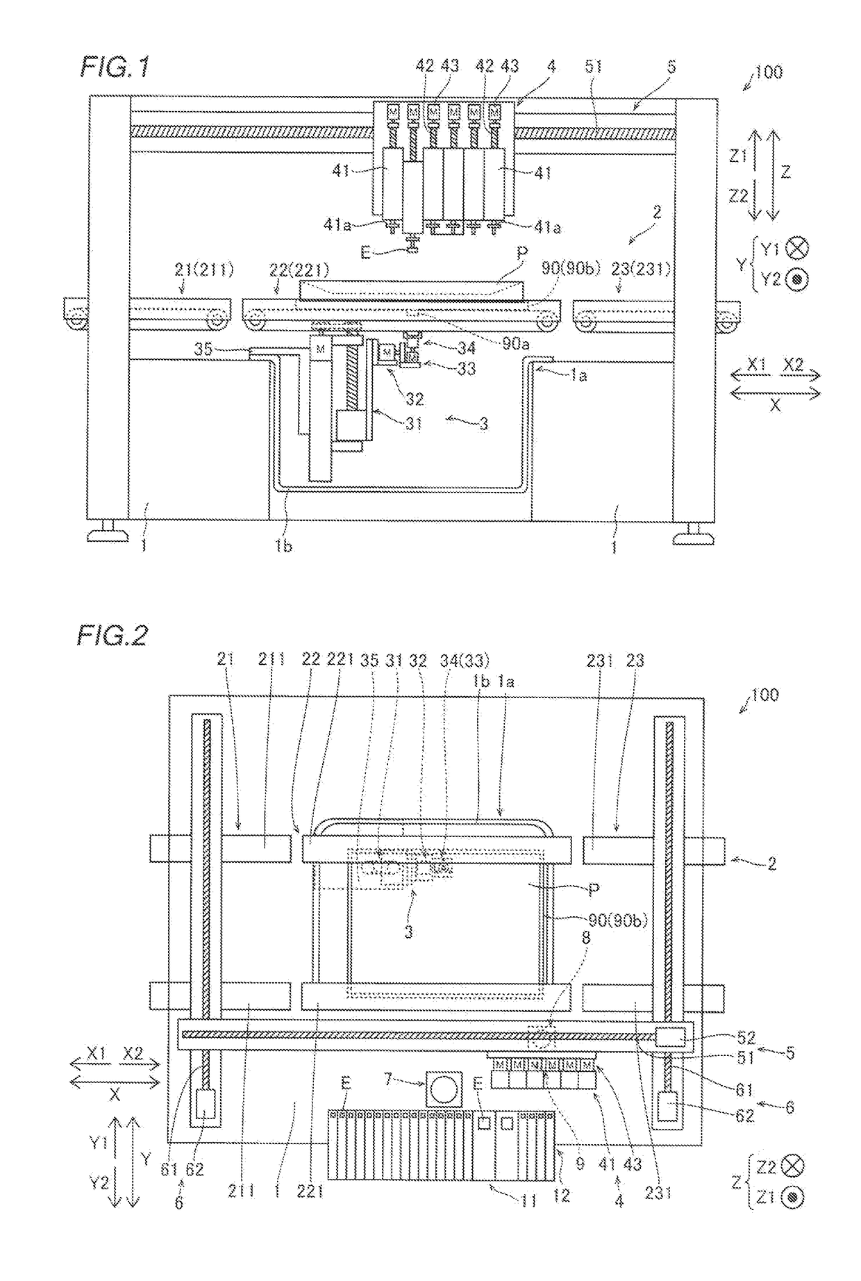
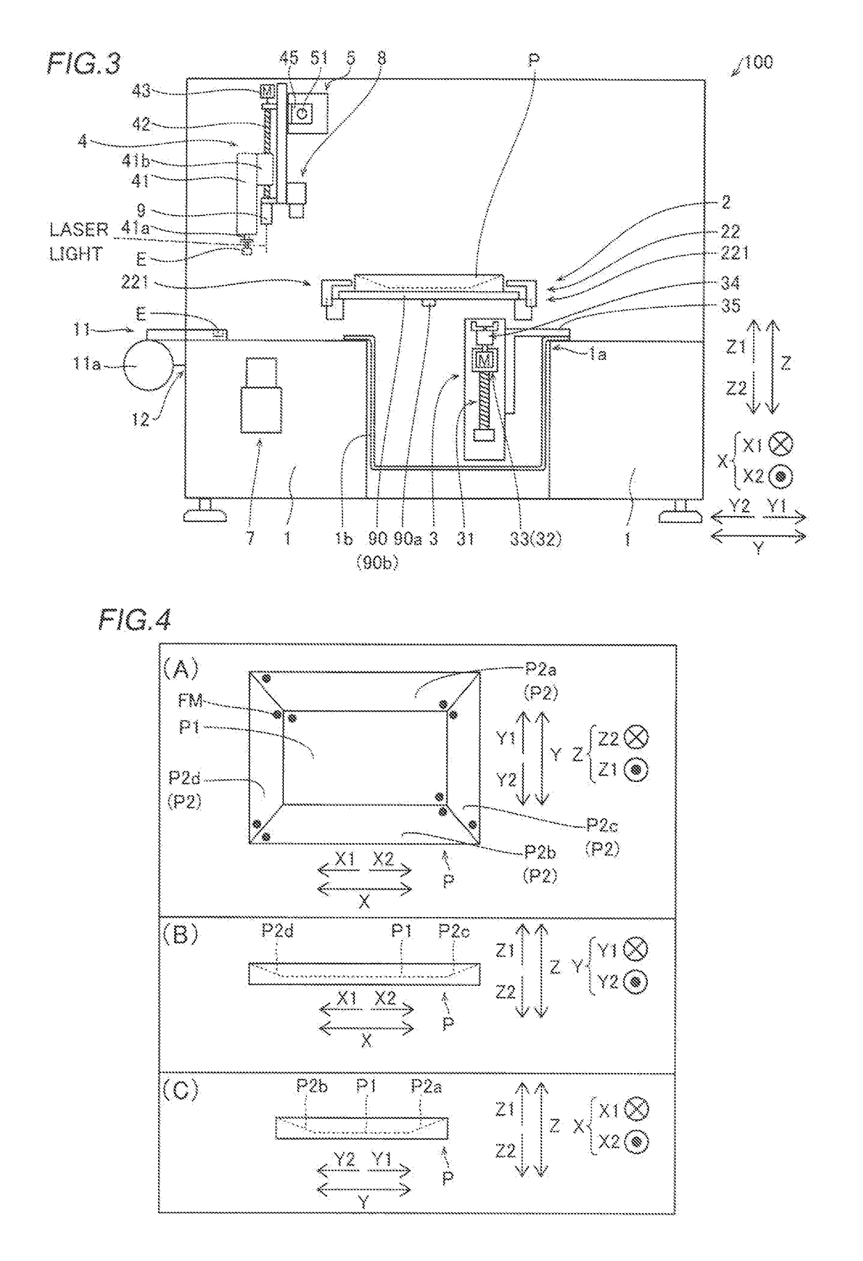
The invention is about a mounting target working device that can hold and support a mounting target. The device has a tilting mechanism and a lifting mechanism. The tilting mechanism can support the rotation mechanism in a way that reduces the need for a complex structure. This design simplifies the device and allows for a smaller mounting target holding unit. Therefore, the invention allows for a mounting target working device that can be easily downsized.

Problems solved by technology

However, in the component mounting device disclosed in the aforementioned Japanese Patent No. 5721469, there is a problem that the holding table rotating device has a structure supported from both sides by the rotating device, and hence it is difficult to downsize the substrate holding device (mounting target holding unit).

Method used


Image

  • Mounting target working device
  • Mounting target working device
  • Mounting target working device

Examples


modified examples

[0115]The embodiment disclosed this time must be considered as illustrative in all points and not restrictive. The range of the present disclosure is shown not by the above description of the embodiment but by the scope of claims for patent, and all modifications (modified examples) within the meaning and range equivalent to the scope of claims for patent are further included.

[0116]For example, while the example in which the present disclosure is applied to the mounting target working device as a component mounting device that mounts components on a mounting target has been shown in the aforementioned embodiment, the present disclosure is not restricted to this. The present disclosure may be applied to a mounting target working device other than the component mounting device.

[0117]For example, the present disclosure may be applied to a mounting target working device as a viscous material application device that applies a viscous material such as solder to a mounting target. In this ...


PUM


Abstract

A mounting target working device includes a mounting target holding unit that holds a mounting target. The mounting target holding unit includes a lift mechanism that moves the mounting target in an upward-downward direction, a tilt mechanism attached to the lift mechanism and that tilts the mounting target, and a rotation mechanism attached to the tilt mechanism and that rotates the mounting target. The rotation mechanism is supported in a cantilever manner by the tilt mechanism.

Description

CROSS-REFERENCE TO RELATED APPLICATION[0001]This application is a National Stage of International Patent Application No. PCT / JP2016 / 050738, filed Jan. 12, 2016, the entire content of which is incorporated herein by reference.BACKGROUNDTechnical Field[0002]The present disclosure relates to a mounting target working device, and more particularly, the present disclosure relates to a mounting target working device that performs work while holding a mounting target.Background Art[0003]In general, a mounting target working device that performs work while holding a mounting target is known. For example, Japanese Patent No. 5721469 discloses a component mounting device (mounting target working device) including a substrate holding device that holds a substrate (mounting target) having a non-flat component mounting surface and a component transfer device that mounts components on the substrate held by the substrate holding device. In this component mounting device, the substrate holding devi...

Claims


Application Information

Patent Timeline
IPC IPC(8): H05K13/04H05K13/08
CPCH05K13/0413H05K13/0812H05K13/0815H05K13/0406H05K13/0419H05K13/0409H05K13/0411H05K13/0069
Inventor OKAZAKI, SHINICHISUZUKI, NAOKI
Owner YAMAHA MOTOR CO LTD
Learn More