
Digital pathological section scanning system

a scanning system and digital technology, applied in the field of section scanning technology, can solve the problems of affecting the final judgment, inaccurate observation results, and inability of physicians to accurately observe the details of cell tissue, so as to improve the definition and readability of digital pathological sections, and improve physician reading efficiency.

Active Publication Date: 2019-02-14
KONFOONG BIOTECH INT
View PDF0 Cites 9 Cited by
  • Summary
  • Abstract
  • Description
  • Claims
  • Application Information

AI Technical Summary

Benefits of technology

The present invention provides a digital pathological section scanning system that can improve the quality of digital pathological sections and eliminate poor quality images. This system aims to improve the efficiency of physicians in reading and interpreting digital pathological sections.

Problems solved by technology

Traditional way of observing a section is carried out by observing the section tissue on a slide through a microscope with a naked eye, which is labor intensive, and the observation result is not very accurate.
However, the existing digital section scanning system typically generates a digital image of the pathological section only according to a scanning result without performing any further processing to the generated image.
In addition, since the image bears rich and complex information, issues listed as follows occur, that is, the image will be partially unclear, the brightness will be uneven and other problems having an influence on the observation of the image will emerge, leading to the result that the physician cannot accurately observe details of the cell tissue somewhere in the image, affecting the final judgment.

Method used


Image

  • Digital pathological section scanning system
  • Digital pathological section scanning system
  • Digital pathological section scanning system

Examples


Embodiment Construction

[0157]The present disclosure will now be described more fully hereinafter with reference to the accompanying drawings, in which exemplary embodiments of the disclosure are shown. This disclosure may, however, be embodied in many different forms and should not be construed as limited to the embodiments set forth herein. Rather, these embodiments are provided so that this disclosure will be thorough and complete, and will fully convey the scope of the disclosure to those skilled in the art. Like reference numerals refer to like elements throughout.

[0158]The terminology used herein is for the purpose of describing particular embodiments only and is not intended to be limiting of the invention. As used herein, the singular forms “a”, “an” and “the” are intended to include the plural forms as well, unless the context clearly indicates otherwise. It will be further understood that the terms “comprises” and / or “comprising,” or “includes” and / or “including” or “has” and / or “having” when use...


PUM

PropertyMeasurementUnit
brightness valueaaaaaaaaaa
brightnessaaaaaaaaaa
sizeaaaaaaaaaa

Abstract

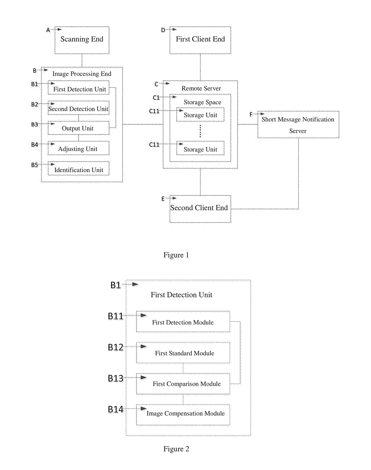
The present invention discloses a digital pathological section scanning system and relates to the field of a section scanning technology. The system comprises a scanning end, an image processing end, a remote server, a first client end and a second client end; wherein, the scanning end scans a pathological section to form an original pathological section image and transmits the original pathological section image to the image processing end for processing; the image processing end processes the original pathological section image to form a digital pathological section image and sends the digital pathological section image to the remote server; the first client end transmits medical record information including attending physician information to the remote server; the remote server associates the digital pathologic section image with the attending physician information and saves the digital pathological section image in the storage unit corresponding to the attending physician information.

Description

CROSS-REFERENCE TO RELATED APPLICATIONS[0001]The present application claims priority to and the benefit of Chinese Patent Application No. CN201710684440.7, filed on Aug. 11, 2017, the entire content of which is incorporated herein by reference.BACKGROUND OF THE INVENTIONField of the Invention[0002]The present invention relates to the field of a section scanning technology, and more particularly, to a digital pathological section scanning system.Description of the Related Art[0003]It is one of the important examination methods to determine if any lesion and abnormity is found in corresponding tissues and organs of human body by observing a section tissue of human body, and such an examination method is usual in the modern medicine. Traditional way of observing a section is carried out by observing the section tissue on a slide through a microscope with a naked eye, which is labor intensive, and the observation result is not very accurate.[0004]With the development of science and tech...

Claims


Application Information

Patent Timeline
Patent Type & Authority Applications(United States)
IPC IPC(8): G06T7/00G06K9/00G06T5/00G06K9/46G06T11/60G16H30/20H04L9/32H04L9/08G01N21/64
CPCG06T7/0012G06K9/00134G06T5/009G06K9/4647G06T11/60G16H30/20H04L9/32H04L9/0838G01N21/6486G01N21/6458G06T2207/10056G06T2207/30024G06T2207/30168G06T2207/20208G06T2210/22G06T2210/41G06T7/0002H04L67/12H04N1/00005H04N1/00018H04N1/00037H04N1/00095H04N1/00244H04N1/04G06T2207/30096G16H30/40G16H10/60A61B5/0059G06V20/693G06T5/92
Inventor LIU, BINGXIANXIE, JUYUANWANG, YANHUI
Owner KONFOONG BIOTECH INT
Learn More