Image processing apparatus, image processing method, and storage medium

a technology of image processing and image processing method, applied in the field of object image processing technique, can solve the problems of large amount of operation in the case of highly accurate three-dimensional shape model generation, insufficient amount of operation for processing object, etc., and achieve the effect of reducing increasing the amount of operation, and high accuracy

Active Publication Date: 2019-02-14
CANON KK
View PDF2 Cites 6 Cited by
  • Summary
  • Abstract
  • Description
  • Claims
  • Application Information

AI Technical Summary

Benefits of technology

[0004]However, a reduction in the amount of operation for processing an object has been insufficient so far. For example, a particle filter used in Japanese Patent Laid-Open No. 2003-271928 is a prediction method based on a probability distribution and a plurality of predicted positions is calculated for each object. Consequently, there has been a possibility that the amount of operation increases in the case where an object is tracked with a high accuracy. Further, even though a method of finding details after finding an outline of a three-dimensional shape model is adopted, the amount of operation in the case where a highly accurate three-dimensional shape model is generated has been still large.

Problems solved by technology

However, a reduction in the amount of operation for processing an object has been insufficient so far.
Further, even though a method of finding details after finding an outline of a three-dimensional shape model is adopted, the amount of operation in the case where a highly accurate three-dimensional shape model is generated has been still large.

Method used


Image

  • Image processing apparatus, image processing method, and storage medium
  • Image processing apparatus, image processing method, and storage medium
  • Image processing apparatus, image processing method, and storage medium

Examples


first embodiment

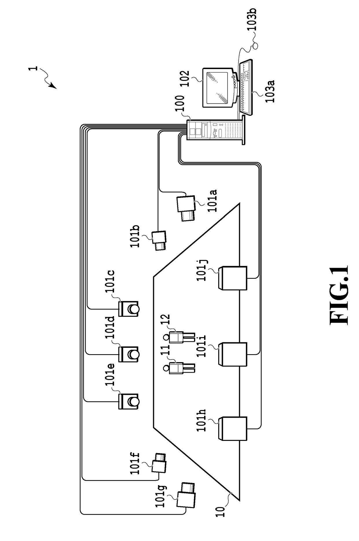
[0017]First, a configuration example of an image processing system 1 according to the present embodiment is explained with reference to FIG. 1. As shown in FIG. 1, each of cameras 101a to 101j is a camera that captures a moving image and arranged facing a field 10 around the field 10, such as an athletic stadium. An image group making up a moving image captured by each of the cameras 101a to 101j is sent out to an image processing apparatus 100. As shown in FIG. 1, in the present embodiment, an example is shown in which persons 11 and 12 moving on the field 10 are objects that are captured by the cameras 101a to 101j.

[0018]First, the image processing apparatus 100 extracts a contour of an object from the image group sent out from each of the cameras 101a to 101j. Next, the image processing apparatus 100 generates a three-dimensional shape model of the object by using the extracted contour. That is, it is possible for the image processing apparatus 100 to generate a three-dimensiona...

second embodiment

[0042]In the first embodiment, the example is mainly explained in which the detection area Ri is set based on the predicted position Qi of an object and the size of the object. In contrast to this, in a tracking method of an object of the present embodiment, it is made possible to dynamically change the detection area Ri for each image. Due to this, it is possible for the image processing apparatus of the present embodiment to track the three-dimensional position of an object with a high accuracy while suppressing a tracking error of an object. In the following, the tracking method of an object in the present embodiment is explained. Explanation of the portions in common to those of the first embodiment is simplified or omitted and in the following, points unique to the present embodiment are explained mainly.

[0043]FIG. 7 is a flowchart showing a setting procedure of the detection area Ri according to the present embodiment. In the present embodiment, in place of S404 in the flowcha...

third embodiment

[0049]Next, an aspect is explained as a third embodiment in which it is possible to track the three-dimensional position of an object with a high accuracy while suppressing a tracking error of the object by rotating the detection area Ri in accordance with the inclination of the axis of the object. Explanation of the portions in common to those of the first and second embodiments is simplified or omitted and in the following, points unique to the present embodiment are explained mainly.

[0050]FIG. 9 is a conceptual diagram showing a setting procedure example of a detection area in the present embodiment. In FIG. 9, an extension of a three-dimensional space at time n is indicated schematically by symbol 900. Further, in FIG. 9, the detection area Ri (n) rotated based on the inclination of an axis 901 of the three-dimensional shape model M (i) is indicated by symbol 902. It may also be possible to acquire the axis 901 of the three-dimensional shape model M (i) by fitting a three-dimens...


PUM


Abstract

The image processing apparatus of the present invention is an image processing apparatus that performs processing relating to a three-dimensional shape model generated by using a plurality of images obtained by a plurality of cameras capturing an object, and the image processing apparatus includes: a specification unit configured to specify, based on position information on an object at a first time, a processing area relating to a three-dimensional shape model of the object at a second time later than the first time; and a processing unit configured to perform processing relating to the three-dimensional shape model of the object at the second time for the processing area specified by the specification unit.

Description

BACKGROUND OF THE INVENTIONField of the Invention[0001]The present invention relates to an image processing technique of an object.Description of the Related Art[0002]In the video image technical field, such as a sports broadcast, an image processing apparatus that assists in tracking an object has been proposed. In such tracking of an object, an object is extracted from an image obtained by capturing a moving person and position information on the extracted object is stored for each image. By referring to such position information on an object, it is possible for the image processing apparatus to acquire, for example, information on the distance traveled by a specific person. Japanese Patent Laid-Open No. 2016-085675 has described preventing a tracking error of an object based on a position relationship of objects making up a group by detecting the group of objects whose amount of change in time of the position relationship is small.[0003]Further, a virtual viewpoint video image sy...

Claims


Application Information

Patent Timeline
Patent Type & Authority Applications(United States)
IPC IPC(8): G06T17/20G06T1/00G06T1/20G06T7/55
CPCG06T17/20G06T1/0007G06T1/20G06T7/55G06T2207/10016G06T2207/30196G06T2207/30232G06T2207/30241G06T7/251G06T7/292
Inventor NISHIYAMA, TOMOHIRO
Owner CANON KK
Why Eureka
Try Eureka