
Vehicle incorporating a deformable front frame structure

Active Publication Date: 2019-02-21
VOLVO CAR CORP
View PDF4 Cites 3 Cited by
  • Summary
  • Abstract
  • Description
  • Claims
  • Application Information

AI Technical Summary

Benefits of technology

The patent text discusses a mounting arrangement for two components that are to be mounted together using a bolt or similar fastening element. In the conventional arrangement, the bolt and holes have the same diameter, and the movement of the components is partially prevented by friction between them. However, in the invention, the cross member is designed to support the transmission unit, which is operatively connected to the electric motor. This design not only prevents vibrations from the transmission unit but also helps to reduce the load on the cross member. In summary, the invention provides improved mounting arrangements for two components and efficient support for transmission units in vehicles.

Problems solved by technology

Electric motors, however, are generally much smaller than the conventional engines, so the same type of engine mounts cannot be used.
Possibly, very large breakable engine / motor mounts could be developed and used, but this would lead to a complex and costly design.

Method used


Image

  • Vehicle incorporating a deformable front frame structure
  • Vehicle incorporating a deformable front frame structure
  • Vehicle incorporating a deformable front frame structure

Examples


Embodiment Construction

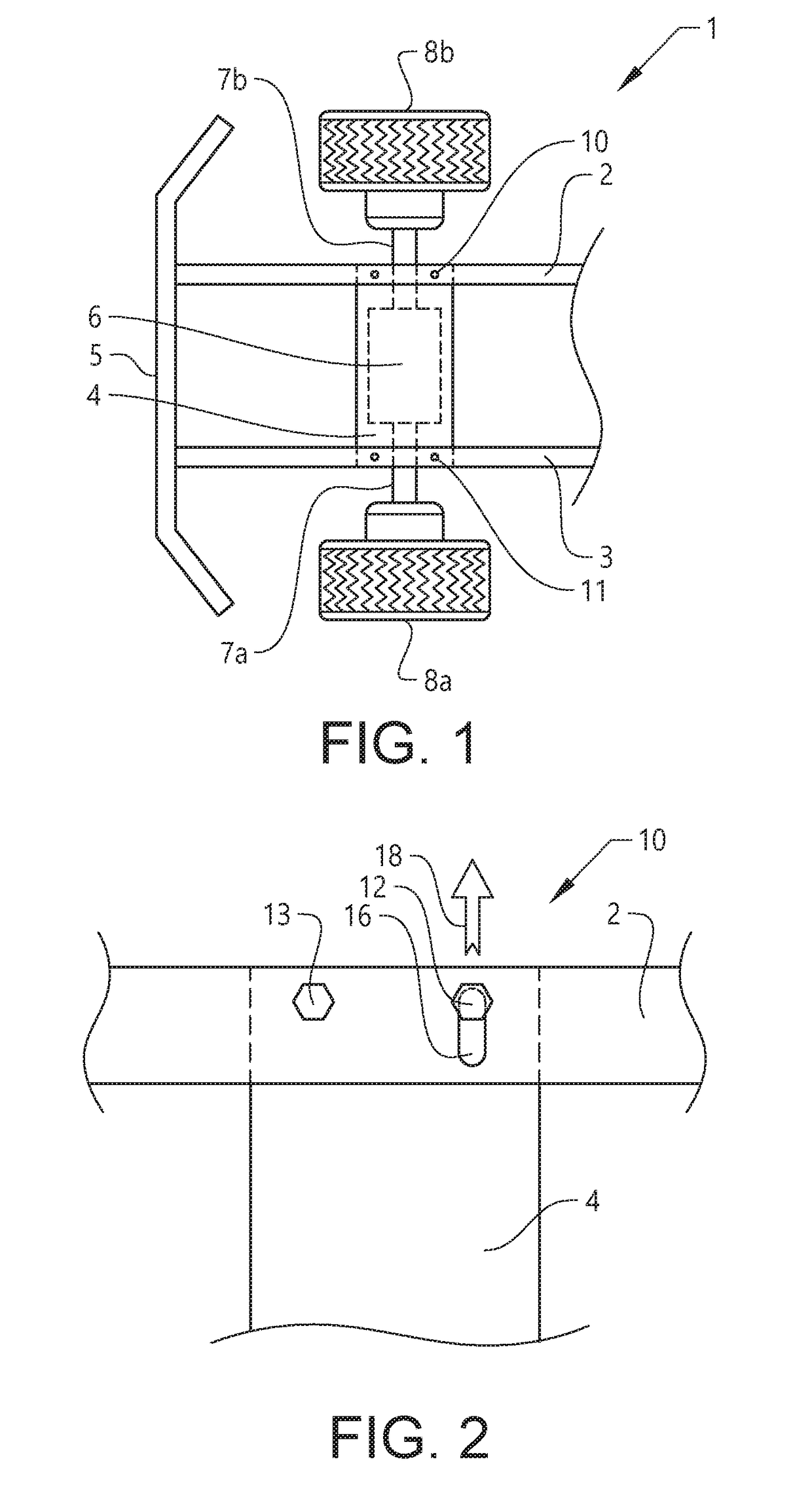
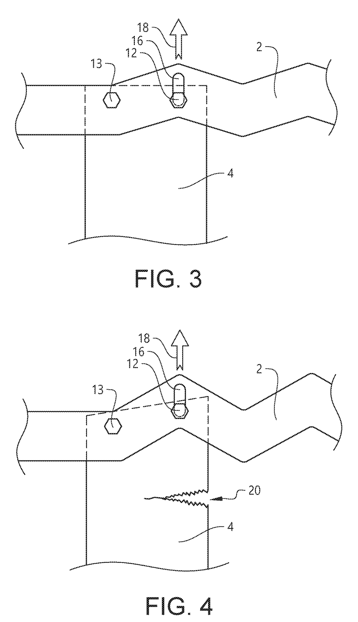
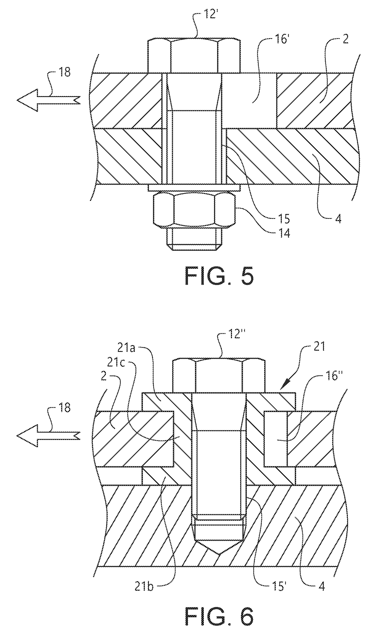
[0046]The invention will now be described with reference to FIGS. 1-6. All figures are more or less schematic and intended to disclose the principle rather than the exact design that may differ depending on the application.

[0047]FIG. 1 shows a top view of a front portion of a passenger vehicle 1. A passenger compartment (not shown) is located to the right. The figure is schematic and shows only a few parts of the front portion. The vehicle 1 is provided with a frame structure including first and second side members 2, 3 extending in a longitudinal direction along opposite sides of the vehicle 1. The frame structure further includes first and second cross members 4, 5 extending in a transversal direction of the vehicle 1 and being connected to the first and second side members 2, 3. The second cross member 5 is arranged at the very front of the frame structure and may be referred to as a bumper beam.

[0048]The vehicle 1 is provided with an electric motor 6 operatively connected via dr...


PUM


Abstract

A vehicle, including: an electric motor operatively connected to at least one driving wheel of the vehicle, and a frame structure including first and second side members extending in a longitudinal direction along opposite sides of the vehicle and at least one cross member extending in a transversal direction of the vehicle and being connected to the first and second side members, wherein the electric motor is supported by the frame structure such that the electric motor is arranged in a front portion of the vehicle in association with a pair of front wheels of the vehicle, and wherein each of the side members, at least along a deformable section thereof, is configured to deform by bending in an inwards and / or outwards transversal direction when compressed by a longitudinally directed force exceeding a threshold value, such as in case the vehicle is subject to a sufficiently energetic frontal collision.

Description

CROSS-REFERENCE TO RELATED APPLICATION[0001]The present patent application / patent claims the benefit of priority of co-pending EP17186569.4, filed on Aug. 17, 2017, and entitled “VEHICLE,” the contents of which are incorporated in full by reference herein.TECHNICAL FIELD[0002]This invention relates to a vehicle incorporating a deformable front frame structure. In particular, the invention relates to how to support an electric motor in the front frame structure of an electric vehicle.BACKGROUND[0003]Electric vehicles are about to form a widespread alternative to vehicles provided with internal combustion engines. The powertrain of an electric vehicle differs from that of a conventional vehicle mainly in that, instead of an internal combustion engine and a gearbox, the electric vehicle is equipped with one or more electric motors operatively connected to the driving wheels of the vehicle and, commonly, a battery pack for storage of electric energy.[0004]This disclosure is concerned wi...

Claims


Application Information

Patent Timeline
IPC IPC(8): B60R19/18B62D21/15B62D25/08B62D21/11
CPCB60R19/18B62D21/152B62D25/085B62D21/11B60R2021/343B60K1/00B62D21/15B60K2001/001
Inventor EHN, JOAKIMBERNDTSSON, CHRISTER
Owner VOLVO CAR CORP
Learn More