Air-foil boundary layer turbine

Inactive Publication Date: 2019-02-21
N4 INNOVATIONS LLC
View PDF4 Cites 0 Cited by
  • Summary
  • Abstract
  • Description
  • Claims
  • Application Information

AI Technical Summary

Benefits of technology

The present invention is a new kind of turbine that combines the benefits of different types of turbines to create a highly efficient working fluid turbine. It has the benefits of a bladed reaction or impulse steam turbine and a boundary layer turbine, which has low entry temperature, simplicity, and durability. The invention optimizes airflow, turbulence, adhesion, surface traction efficiency, and strengthens the structure while also stabilizing destructive blade oscillations observed in conventional boundary layer turbines when operating at high revolutions. This results in a boundary layer turbine that is much more effective at converting energy from fluid to electricity.

Problems solved by technology

Moreover, the high internal temperature, pressure and rotational stresses experienced under long-term use can cause the rotor discs to fracture and otherwise fail.
Conventional bladed steam turbines require Rankine cycle entry point temperatures above 1,049° F., or otherwise they must lower the fluid boiling point by use of Organic Rankine Cycle fluids, which adulterates the pure working fluid, require special materials, and add to design complexity required for successful operation.

Method used


Image

  • Air-foil boundary layer turbine
  • Air-foil boundary layer turbine
  • Air-foil boundary layer turbine

Examples


Embodiment Construction

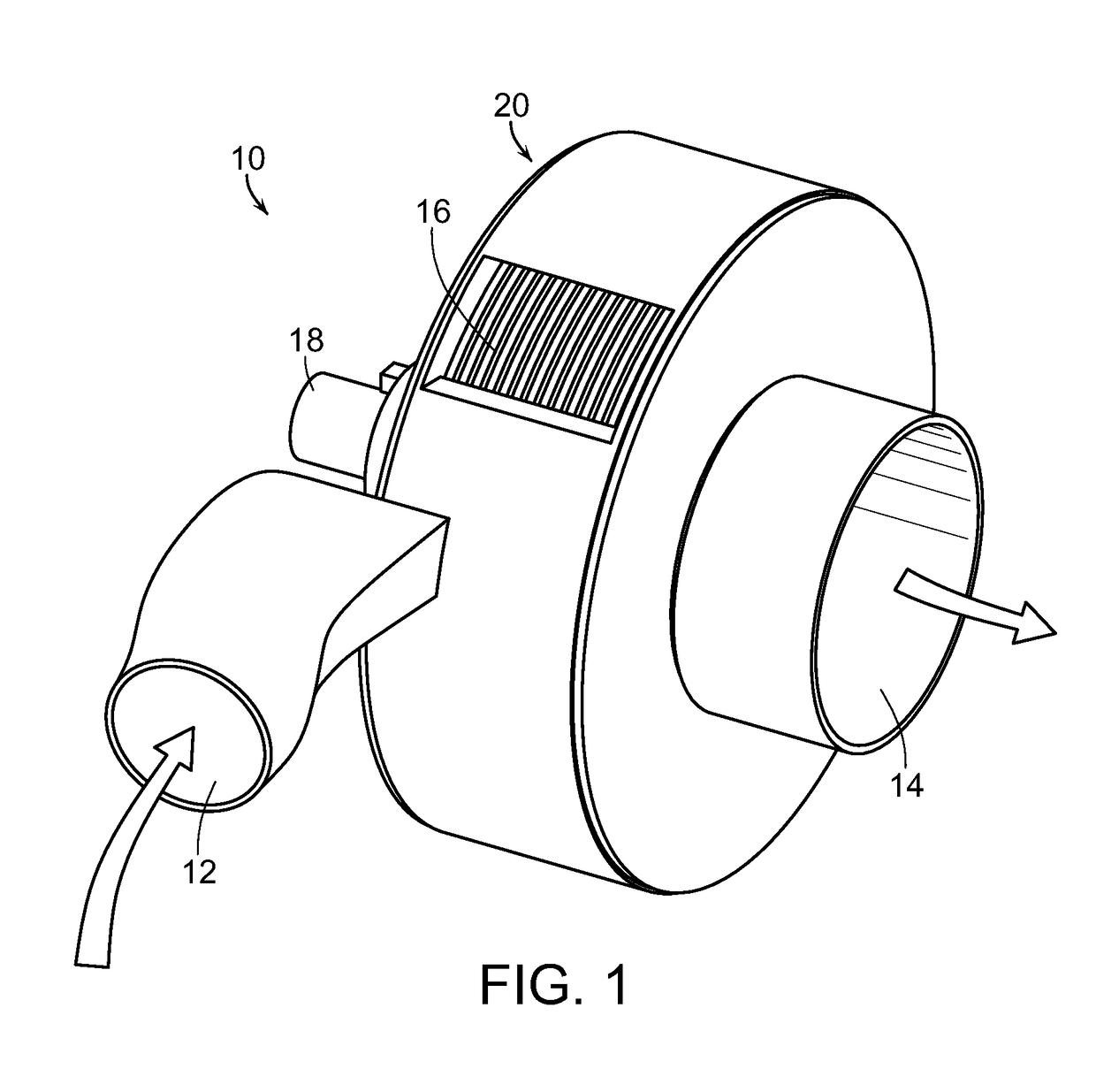
[0019]As shown in the accompanying drawings, for purposes of illustration, the present invention resides in an improved boundary layer turbine, generally referred to by the reference number 10. The turbine 10 of the present invention has hybridized traits of different turbine types, including an airfoil boundary layer turbine that combines the desirable high efficiency characteristics of a bladed reaction or impulse steam turbine with the relatively low entry temperature, simplicity and durability of a boundary layer turbine. The turbine 10 of the present invention optimizes internal air flow resistance, turbulence, adhesion, and surface traction efficiency while strengthening the blade structure and stabilizing destructive blade oscillations observed in conventional boundary layer turbines when operating at high revolutions.

[0020]With reference now to FIG. 1, an exemplary turbine 10 embodying the present invention is shown. The turbine 10 includes a fluid inlet 12 and a fluid outle...


PUM


Abstract

A boundary layer turbine includes a housing having a fluid inlet and a fluid outlet and a rotatable shaft at least partially disposed within the housing. Two or more rotor discs are coupled to the shaft in spaced relation to one another. Spacers are attached to at least a plurality of the rotor discs. The spacers are configured so as to provide a lifting force as fluid is passed over the spacers. An inner surface of the housing as well as the outer 25% of the disc surface may have spaced apart depressions formed thereon to assist in fluid flow passing more freely between the housing and the rotor discs, as well as along the outer leading edge of the disk.

Description

BACKGROUND OF THE INVENTION[0001]The present invention generally relates to turbines. More particularly, the present invention relates to an improved boundary layer turbine having spacers configured to provide a lifting force as fluid passes over the spacers to combine desirable high-efficiency characteristics of a bladed reaction or impulse steam turbine with the relatively low entry temperature, simplicity and durability of a boundary layer turbine.[0002]A boundary layer turbine uses the boundary layer effect and not a fluid impinging upon the blades as in a conventional turbine. Such turbines are sometimes referred to as a Tesla turbine, which is a bladeless centripetal flow turbine, invented by Nikola Tesla in the early 1900s. A boundary layer turbine, or Tesla turbine, consists of a set of smooth discs with nozzles applying a moving fluid to the edge of the disc. The fluid drags on the disc by means of viscosity and the adhesion of the surface layer of the fluid. As the fluid s...

Claims


Application Information

Patent Timeline
IPC IPC(8): F01D1/36F01D5/04
CPCF01D1/36F01D5/048F05D2220/31F05D2240/24
Inventor BERKSON, BRUCE RICHARDCHASE, RONALD J.
Owner N4 INNOVATIONS LLC
Why Eureka
Try Eureka