Acoustic wave device

Active Publication Date: 2008-07-24
TAIYO YUDEN KK
View PDF6 Cites 9 Cited by
  • Summary
  • Abstract
  • Description
  • Claims
  • Application Information

AI Technical Summary

Benefits of technology

[0009]The present invention has been made in view of the above circumstance and provides an acoustic wave device having a strengthened structure realized by a high yield.

Problems solved by technology

However, the acoustic devices formed by the arts disclosed in documents D1 through D4 have a disadvantage that the devices does not withstand pressure applied at the time of modularizing and a ceiling portion of the cavity structure is concaved.
However, an increased amount of resin for the purpose of obtaining an increased thickness of the ceiling portion of the cavity structure may degrade the yield.

Method used


Image

  • Acoustic wave device
  • Acoustic wave device
  • Acoustic wave device

Examples


first embodiment

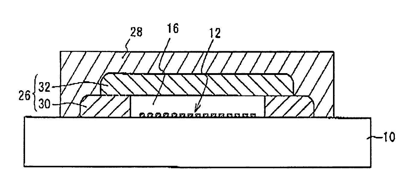
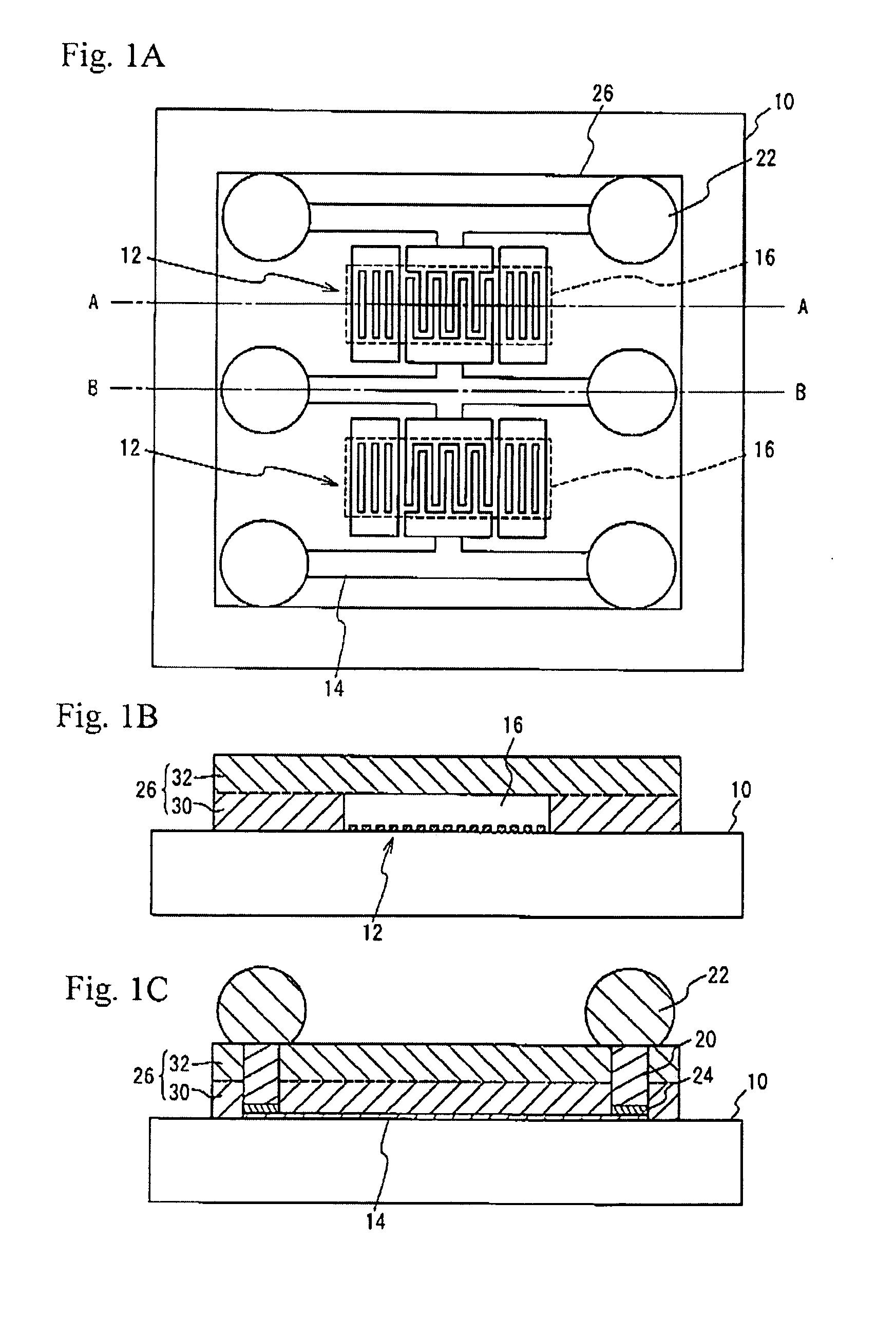
[0040]FIG. 7A is a plan view of an acoustic wave device in accordance with a first embodiment. FIG. 7B is a cross-sectional view taken along a line A-A shown in FIG. 7A, and FIG. 7C is a cross-sectional view taken along a line B-B shown in FIG. 7A. In FIG. 7A, there are illustrated the acoustic wave elements 12, the interconnection lines 14 and the cavities 16 seen through the first seal portion 26 and the second seal portion 28. The acoustic wave elements 12 and the interconnection lines 14 are illustrated by solid lines, and the cavities 16 and the first seal portion 26 are illustrated by broken lines.

[0041]Referring to FIGS. 7A and 7B, each of the acoustic wave element 12 includes an IDT and reflectors formed by a metal film on the piezoelectric substrate 10. The first seal portion 26 is provided on the piezoelectric substrate 10 so as to have the cavities 16 located above the functional portions of the acoustic wave elements 12. The first seal portion 26 has the third seal porti...


PUM


Abstract

An acoustic wave device includes an acoustic wave element formed on a substrate, a first seal portion provided on the substrate so as to form a cavity above the acoustic wave element, and a second seal portion provided on the first seal portion, the first seal portion having a step so that the first seal portion has a width on a first side and another width on a second side arranged so that the first side is closer than the second side to the substrate, and the width on the first side is greater than the another width on the second side.

Description

BACKGROUND OF THE INVENTION[0001]1. Field of the Invention[0002]The present invention generally relates to acoustic wave devices, and more particularly, to an acoustic wave device having a seal portion having a cavity located above an acoustic wave element.[0003]2. Description of the Related Art[0004]A surface acoustic wave device (SAW device) is capable of exciting an acoustic wave by applying power to comb electrodes of an interdigital transducer (IDT) formed on a piezoelectric substrate. The SAW device is widely used for various circuits that process radio signals in a frequency band of for example, 45 MHz to 2 GHz. Examples of these circuits are bandpass filters for transmission, bandpass filters for reception, local oscillation filters, antenna duplexers, intermediate frequency filters, and FM modulators.[0005]Recently, an acoustic wave device using a film bulk acoustic resonator (FBAR) has been developed. The FBAR has a pair of electrodes provided on opposite surfaces of a pie...

Claims


Application Information

Patent Timeline
IPC IPC(8): H01L41/08
CPCH03H3/08H01L2224/11H03H9/25
Inventor TSUDA, KEIJIKIMURA, JYOUJIAIKAWA, SHUNICHIINOUE, KAZUNORIMATSUDA, TAKASHI
Owner TAIYO YUDEN KK
Why Eureka
Try Eureka