Braking control device for vehicle

a technology for controlling devices and vehicles, applied in the direction of brake systems, brake-by-wire, etc., can solve the problems of operator's perception of oddness, vehicle deceleration, and deviation between the operator's expected operation and the actual vehicle behavior, and achieve the effect of improving the braking response of the vehicle and simple configuration

Active Publication Date: 2019-02-28
MAZDA MOTOR CORP
View PDF12 Cites 2 Cited by
  • Summary
  • Abstract
  • Description
  • Claims
  • Application Information

AI Technical Summary

Benefits of technology

[0008]Therefore, one purpose of the present disclosure is to provide a braking control device for a vehicle, which can eliminate a deviation between an expected operation of a vehicle operator and behavior of the vehicle, without depending on an operating situation of a brake pedal.
[0011]The braking rigidity characteristic setting part may set a local minimum point where the braking rigidity becomes the minimum within a range of near-zero deceleration, and set the reaction force so that the braking rigidity decreases as the deceleration of the vehicle becomes larger when the deceleration of the vehicle is smaller than the local minimum point. According to this configuration, a situation where a vehicle operator's perception of stepping of the brake pedal becomes slow, regardless of the deceleration occurring on the vehicle, can be avoided.
[0012]The braking rigidity characteristic setting module may set the local minimum point within a range near a minimum threshold of the deceleration that is perceivable by a vehicle operator. According to this configuration, a situation where the operator's perception of the stepping of the brake pedal becomes slow can be avoided, without needing a highly precise adjustment.
[0013]The local minimum point may be set within a deceleration range higher than a minimum threshold of the deceleration that is perceivable by a vehicle operator. According to this configuration, the vehicle operator can foresee an actual start of the stepping operation of the brake pedal upon the operation accompanied by a negative braking rigidity, while improving a braking response of the vehicle.

Problems solved by technology

Therefore, there is a possibility that a deviation may arise between the operator's expected operation and the actual vehicle behavior as the stepping operation feel is changed based on the mechanical play of the brake mechanism.
For this reason, although the operator recognizes that the actual stepping stroke starts from a point of inflection where the characteristic related to the rigid feel changes from negative to positive, the vehicle starts decelerating when the stroke of the brake pedal occurs, and thereby, the operator may feel odd.

Method used


Image

  • Braking control device for vehicle
  • Braking control device for vehicle
  • Braking control device for vehicle

Examples


Embodiment Construction

[0020]Hereinafter, one embodiment of the present disclosure is described in detail based on the accompanying drawings. The following description merely illustrates the present disclosure being applied to a braking control device for a vehicle, and thus, this description is not to limit the present disclosure, its applications, and its use.

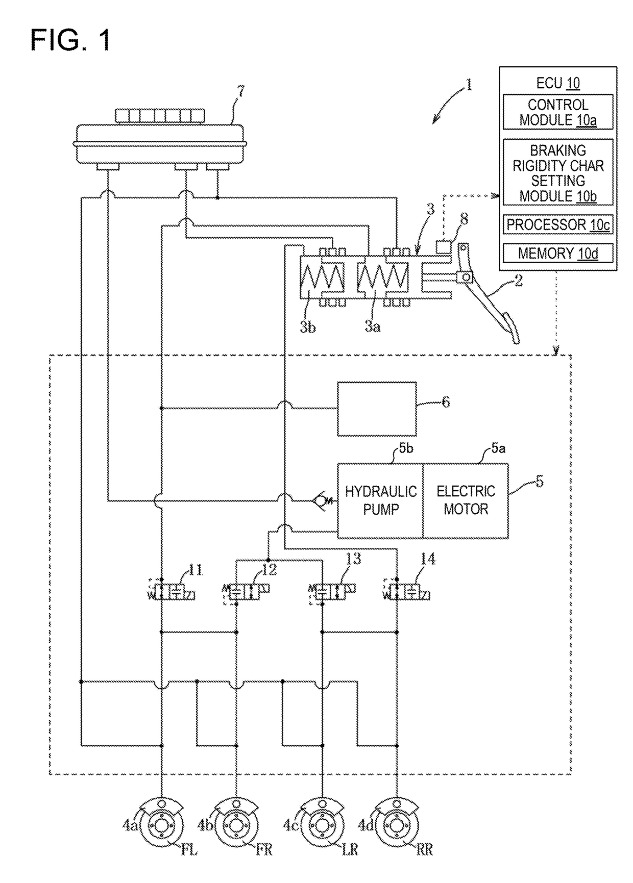
[0021]Below, one embodiment of the present disclosure is described based on FIGS. 1 to 5. As illustrated in FIG. 1, a braking control device 1 constitutes a brake-by-wire mechanism, and includes a master cylinder 3 capable of generating brake hydraulic pressure corresponding to a stroke (stepping state) of a brake pedal 2, and a braking hydraulic pressure generating mechanism 5 (braking-force generating part) capable of supplying brake hydraulic pressure to wheel cylinders 4a-4d which respectively brake the rotations of front and rear, and left and right wheels FL, FR, RL, and RR of a vehicle. The device 1 is configured so that, when the braking hy...


PUM


Abstract

A braking control device for a vehicle is provided, which includes an operating amount detecting part configured to detect an operating amount of a brake pedal, a reaction-force giving part configured to generate a reaction force of the brake pedal, a braking-force generating part configured to generate a braking force for wheels according to the brake pedal operating amount, and an electronic control unit (ECU) electrically connected with them. The ECU includes a processor configured to control the giving part and generating part, and set a braking rigidity characteristic based on a braking rigidity that is a ratio of the reaction force to the operating amount, and a vehicle deceleration. The ECU sets a braking rigidity value so that the braking rigidity value increases as the vehicle deceleration becomes larger. The ECU controls the reaction-force giving part based on the braking rigidity value.

Description

TECHNICAL FIELD[0001]The present disclosure relates to a braking control device for a vehicle, and particularly to the braking control device provided with a reaction-force giving part which generates a reaction force based on an operating amount of a brake pedal and a braking-force generating part which generates a braking force for wheels.BACKGROUND OF THE DISCLOSURE[0002]Conventionally, vehicles with a by-wire system are known, which are provided with an operating mechanism operated by a vehicle operator, a reaction-force generating mechanism which gives an operational reaction force to the operating mechanism, and a driving mechanism which drives a vehicle so that the vehicle functions by a given response amount according to the operating amount to the operating mechanism. In such vehicles which adopt the by-wire system, the coupling with a mechanical mechanism between the operating mechanism and the driving mechanism is replaced with a coupling by an electrical signal so that t...

Claims


Application Information

Patent Timeline
Patent Type & Authority Applications(United States)
IPC IPC(8): B60T8/40B60T8/32B60T8/17
CPCB60T8/4081B60T8/326B60T8/17B60T2270/82B60T8/171B60T8/3255B60T8/409
Inventor KAIHARA, SHINICHIMOCHIZUKI, HIROTAKAKYUTO, NOBORUIMAI, KATSUHISATAKEMURA, KAZUHIROYAMADA, NAOKITANGO, YUTAKAMURA, TAKANOBU
Owner MAZDA MOTOR CORP
Why Eureka
Try Eureka