Shock-absorbing packing box

Active Publication Date: 2019-02-28
RECO
View PDF4 Cites 2 Cited by
  • Summary
  • Abstract
  • Description
  • Claims
  • Application Information

AI Technical Summary

Benefits of technology

[0014]In accordance with a shock-absorbing packing box in accordance with the present disclosure, a shock-absorbing packing material having a plurality of air cell structures may be formed into a box shape to form the shock-absorbing packing box, thereby providing a packing means having a stable structure with a box shape and concurrently more safely protecting an article accommodated in the box through the plurality of air cell structures.
[0015]Furthermore, in a case in which a shock-absorbing packing box is formed using a shock-absorbing packing material having a plurality of air cells formed in a multi-layered structur

Problems solved by technology

In this case, since the paper box only packs the article and does not provide a shock-absorbing and protecting function, the article is easily damaged by an external impact or the like during transportation of the paper box.
Therefore, when an article is easily damaged or likely to be damaged during transportation thereof, it is necessary to protect the article from an external impact.
However, it is difficult to accommodate and pack articles having various shapes such as cylindrical or hexahedral articles.
However, since a plurality of a small-sized air caps are used and a non-sho

Method used


Image

  • Shock-absorbing packing box
  • Shock-absorbing packing box
  • Shock-absorbing packing box

Examples


first embodiment

[0033]Hereinafter, a shock-absorbing packing box in accordance with the present disclosure will be described.

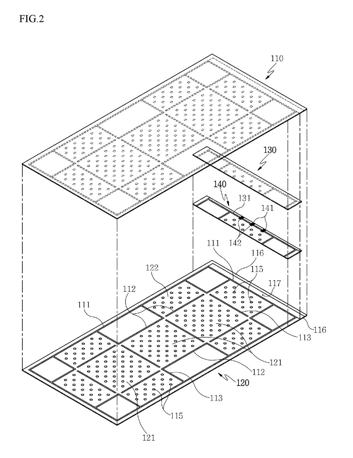
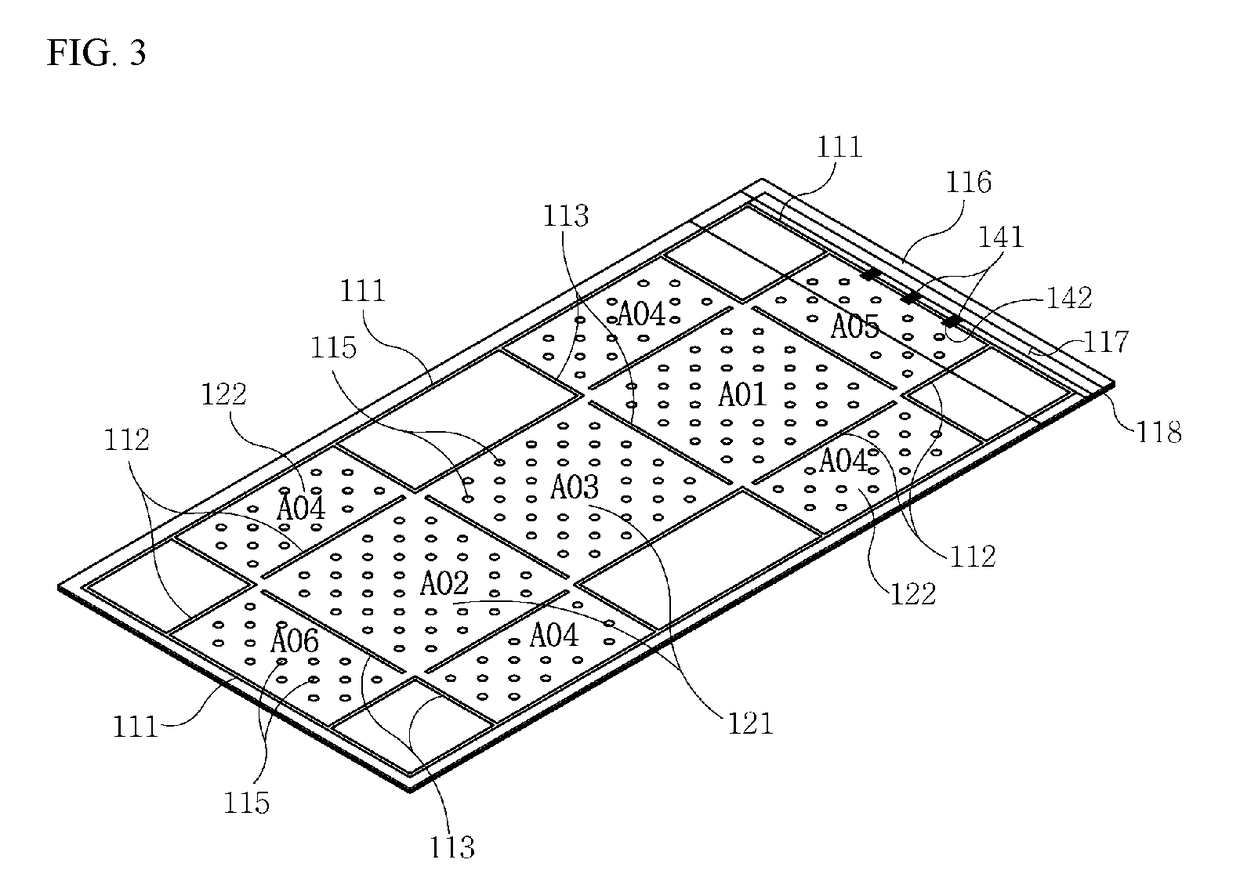
[0034]FIG. 2 is an exploded perspective view illustrating a configuration of a shock-absorbing packing material constituting the shock-absorbing packing box in accordance with the first embodiment of the present disclosure. FIG. 3 is a development view illustrating the shock-absorbing packing material constituting the shock-absorbing packing box in accordance with the first embodiment of the present disclosure. FIGS. 4 and 5 are views illustrating processes of forming the shock-absorbing packing box through the shock-absorbing packing material developed in the first embodiment of the present disclosure.

[0035]As illustrated in FIGS. 2 to 5, the shock-absorbing packing box in accordance with the first embodiment of the present disclosure includes the shock-absorbing packing material. The shock-absorbing packing material includes an upper outer shell 110 and a lower outer shell ...

second embodiment

[0057]As illustrated in FIGS. 6 to 9, the shock-absorbing packing box in accordance with the present disclosure includes the shock-absorbing packing material. The shock-absorbing packing material includes an upper outer shell 210 and a lower outer shell 220 which are partially fused to each other to form a plurality of first air cells 213 extending in a lengthwise direction, i.e., a longitudinal direction of the outer shells at a central portion of the outer shells, to form a plurality of second air cells 216 spaced apart from each other by a certain distance in the lengthwise direction of the outer shells at both sides of the central portion of the outer shells, and to form an air injection path 223 configured to inject air into the first and second air cells 213 and 216 at a front end of the outer shells; and an upper inner shell 230 and a lower inner shell 240 which are interposed between the upper outer shell 210 and the lower outer shell 220 and are partially fused to each othe...


PUM


Abstract

Provided is a shock-absorbing packing box, in which a pair of inner shells are partially fused between a pair of outer shells to constitute a shock-absorbing packing material having a plurality of air cells, and when air is filled into the air cells, the plurality of air cells filled with the air are connected in an overall box-shaped structure.

Description

TECHNICAL FIELD[0001]The present disclosure relates to a shock-absorbing packing box, and more particularly, to a shock-absorbing packing box, in which a pair of inner shells are partially fused between a pair of outer shells to constitute a shock-absorbing packing material having a plurality of air cells, and when air is filled into the air cells, the plurality of air cells filled with the air are connected in an overall box-shaped structure, whereby a packing means having a stable structure with a box shape is provided, and concurrently, shock-absorbing performance is improved, and furthermore, when the shock-absorbing packing material forming the shock-absorbing packing box is formed, at least one auxiliary inner shell is additionally provided so as to be alternately and partially fused with the pair of outer shells between the pair of outer shells forming the air cells, to constitute a shock-absorbing packing material having a plurality of air cells formed in a multi-layered str...

Claims


Application Information

Patent Timeline
IPC IPC(8): B65D81/02B65D81/03B65D85/30B29D22/02F16F9/04
CPCB65D81/022B65D81/03B65D85/30B29D22/02F16F9/04B65D81/052B29D22/003
Inventor KIM, YOUNG SOO
Owner RECO
Why Eureka
Try Eureka