Light amount control mechanism for vehicle headlight

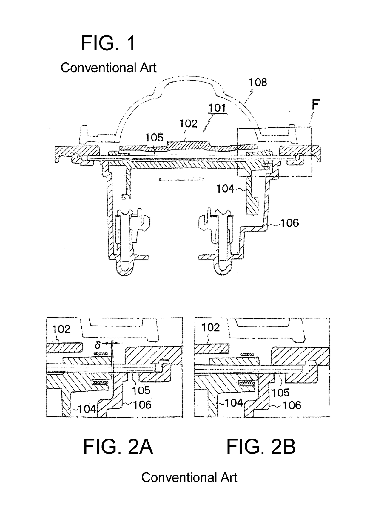
a control mechanism and headlamp technology, applied in the direction of vehicle components, signalling/lighting devices, lighting and heating apparatus, etc., can solve the problems of uneven rotation of the movable shade b, 102/b>, and achieve the effect of suppressing the variation of light distribution due to the movable shade and stable rotation of the movable shad

Active Publication Date: 2019-02-28
STANLEY ELECTRIC CO LTD
View PDF0 Cites 0 Cited by
  • Summary
  • Abstract
  • Description
  • Claims
  • Application Information

AI Technical Summary

Benefits of technology

[0010]The presently disclosed subject matter was devised in view of these and other problems and features in association with the conventional art. According to an aspect of the presently disclosed subject matter, there can be provided a light amount control mechanism for a vehicle headlamp that can maintain high positional precision of a movable shade in its rotation axis direction to suppress variation in light distribution while allowing stable rotation of the movable shade.
[0014]According to the aforementioned aspect of the presently disclosed subject matter, in a state in which the movable shade is rotated to be positioned at the first position or the second position, the V-shaped convex portion formed on one of the movable shade on the rotation side and the housing on the stationary side can engage with the V-groove-shaped concave portion formed on the other of them, so that the positioning of the movable shade in the rotation axis direction is precisely achieved. Therefore, a backlash in the rotation axis direction cannot be generated in the movable shade, so that variations in light distribution due to the movable shade can be suppressed. Since the positioning of the movable shade in the rotation axis direction is precisely achieved in this manner, a predetermined axial gap can be set between the movable shade on the rotation side and the housing on the stationary side. This can ensure the stable rotation of the movable shade due to this axial gap.

Problems solved by technology

In order to solve the above-mentioned problem, as illustrated in FIG. 2B, it is conceivable that an axial gap is not provided between the bracket 104 and the housing 106; however, when the axial gap is not provided, another problem arises that the rotation of the movable shade 102 is not smoothly performed particularly when the bracket 104 and the housing 106 are heated and thermally expanded.

Method used


Image

  • Light amount control mechanism for vehicle headlight
  • Light amount control mechanism for vehicle headlight
  • Light amount control mechanism for vehicle headlight

Examples


first exemplary embodiment

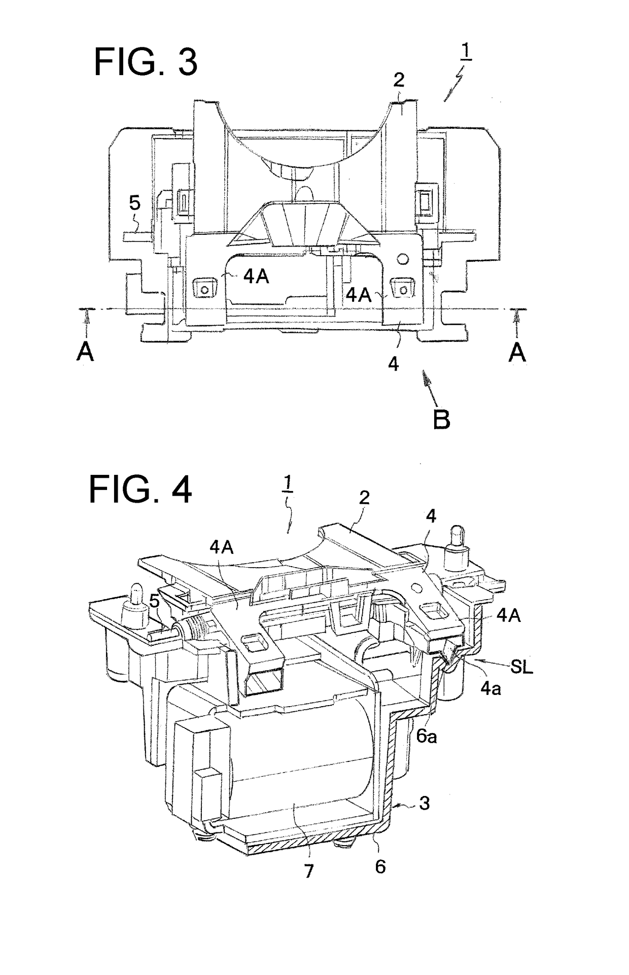
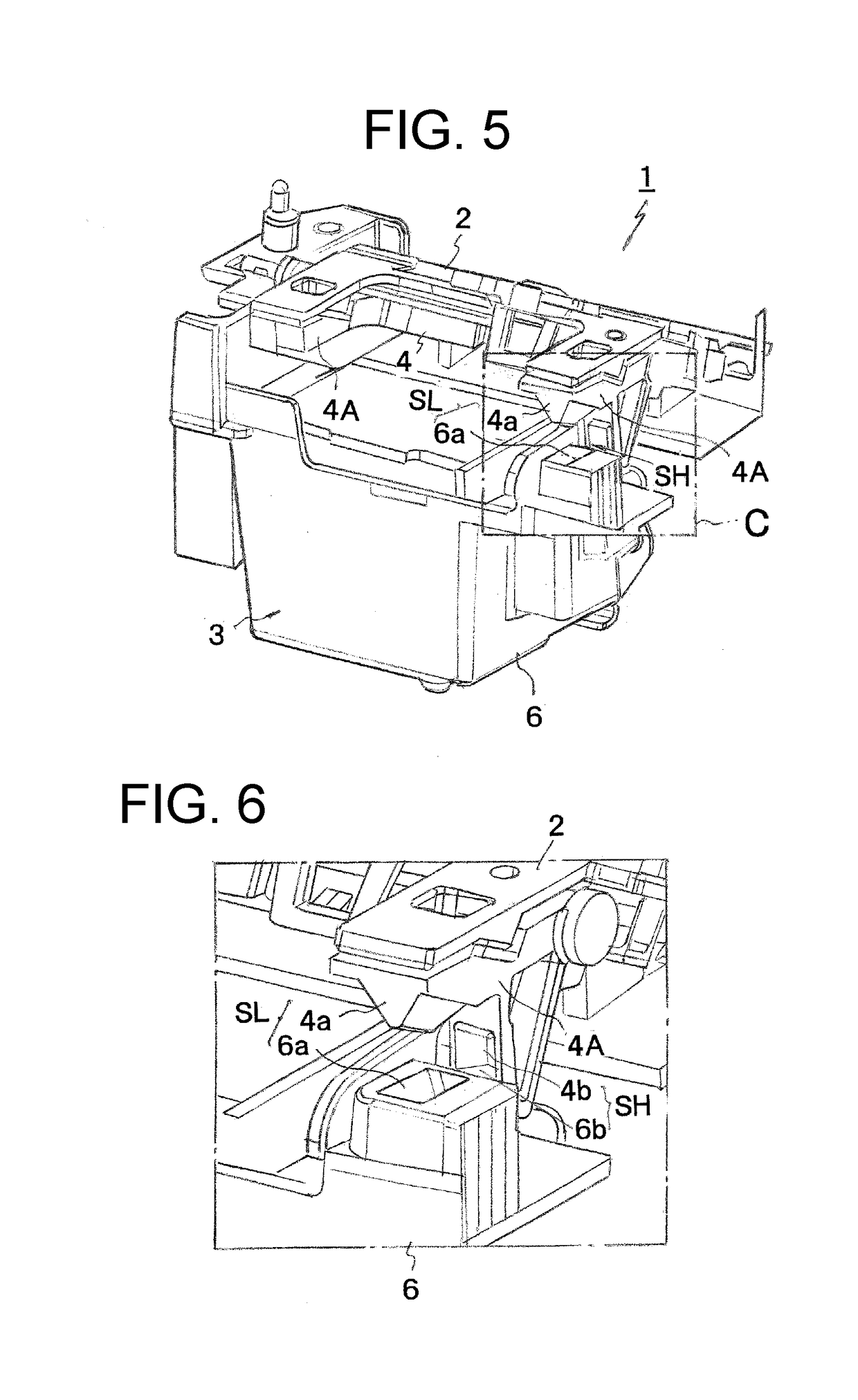
[0030]FIG. 3 is a plan view of a light amount control mechanism made in accordance with the principles of the presently disclosed subject matter according to a first exemplary embodiment; FIG. 4 is a perspective view when the light amount control mechanism of FIG. 3 is cut along line A-A and viewed in an oblique direction; FIG. 5 is a perspective view of the light amount control mechanism of FIG. 3 when viewed in an arrow B direction in FIG. 3; and FIG. 6 is an enlarged detailed view of a portion C of FIG. 5.

[0031]The light amount control mechanism 1 according to the present exemplary embodiment can be provided to each headlamp (not illustrated) disposed on the left and right of the front of the vehicle. The light amount control mechanism 1 can include a movable shade 2 configured to rotatably move and switch the shielding amount of light emitted from a light source (not illustrated), and an actuator 3 configured to drive the movable shade 2. Here, the movable shade 2 can be configu...

second exemplary embodiment

[0038]A description will now be given below of a light amount control mechanism for a vehicle headlight of the presently disclosed subject matter with reference to FIGS. 7 to 9 as a second exemplary embodiment. FIG. 7 is an explanatory view showing the engagement state of a concave portion and a convex portion in a low beam stopper portion of a light amount control device according to the second exemplary embodiment of the presently disclosed subject matter, FIG. 8 is a cross-sectional view taken along line D-D of FIG. 7, and FIG. 9 is an explanatory view showing the engagement state of a concave portion and a convex portion in the high beam stopper portion of the light amount control device according to the second exemplary embodiment.

[0039]In the present exemplary embodiment, similarly to the first exemplary embodiment, the light amount control mechanism 1 may be provided with a low beam stopper SL and a high beam stopper SH for positioning and holding the movable shade 2 at the f...

third exemplary embodiment

[0042]A description will now be given below of a light amount control mechanism for a vehicle headlight of the presently disclosed subject matter with reference to FIGS. 10 to 12 as a third exemplary embodiment.

[0043]FIG. 10 is an explanatory view illustrating an engagement state of a concave portion and a convex portion in a low beam stopper portion of a light amount control mechanism according to the third exemplary embodiment of the presently disclosed subject matter, FIG. 11 is an explanatory view showing the engagement state of a concave portion and a convex portion in a high beam stopper portion of the light amount control mechanism according to the third exemplary embodiment, and FIG. 12 is a cross-sectional view taken along line E-E of FIG. 11. In these drawings, the same reference numerals are assigned to the same elements as those shown in FIGS. 7 to 9, and descriptions thereof will be omitted.

[0044]The present exemplary embodiment is configured such that, as shown in FIG....


PUM


Abstract

A light amount control mechanism for a vehicle headlamp can maintain high positional precision of a movable shade in its rotation axis direction to suppress variation in light distribution while allowing stable rotation of the movable shade. The light amount control mechanism includes a movable shade configured to be rotatably supported by a housing and selectively pivots to a first position or a second position to switch a shielding amount of light emitted from a light source, and an actuator configured to drive the movable shade. The light amount control mechanism for a vehicle headlamp may further include a stopper configured to position and hold the movable shade at the first position and the second position, the stopper being constituted by a V-shaped convex portion formed on any one of the movable shade and the housing and a V-groove-shaped concave portion formed on the other thereof as a pair.

Description

[0001]This application claims the priority benefit under 35 U.S.C. § 119 of Japanese Patent Application No. 2017-160849 filed on Aug. 24, 2017, which is hereby incorporated in its entirety by reference.TECHNICAL FIELD[0002]The presently disclosed subject matter relates to a light amount control mechanism for a vehicle headlamp for switching a shielding amount of light emitted from a light source.BACKGROUND ART[0003]In some headlamps arranged on the left and right sides of the front portion of a vehicle, a light amount control mechanism for switching the amount of shielding of light emitted from the light source can be provided. Examples of such headlamps may include those described in Japanese Patent Application Laid-Open Nos. 2014-002963, 2014-007048, and 2015-046341.[0004]Such a light amount control mechanism can include a movable shade configured to rotatably switch a shielding amount of light emitted from a light source, and an actuator configured to drive the movable shade. In ...

Claims


Application Information

Patent Timeline
Patent Type & Authority Applications(United States)
IPC IPC(8): F21S41/692F21S41/40
CPCF21S41/692F21S41/40F21S41/689
Inventor ZANMA, YASUYUKI
Owner STANLEY ELECTRIC CO LTD
Why Eureka
Try Eureka