Atomic oscillator

a technology of atomic oscillators and oscillators, which is applied in the direction of oscillator generators, apparatus using atomic clocks, pulse automatic control, etc., can solve the problem that atom cells cannot be disposed on the substrate with high positional precision, and achieve the effect of high positional precision

Active Publication Date: 2019-05-16
MICROCHIP TECH INC
View PDF2 Cites 0 Cited by
  • Summary
  • Abstract
  • Description
  • Claims
  • Application Information

AI Technical Summary

Benefits of technology

[0024]In the frequency signal generation system according to this application example, which includes the thermally insulating member, which is fixed to the substrate and positions the container, heat transfer between the substrate and the atom cell can be suppressed, and the container can be positioned with high positional precision with respect to the substrate.

Problems solved by technology

Otherwise, an atom cell cannot be disposed on the substrate with high positional precision in some cases.

Method used


Image

  • Atomic oscillator
  • Atomic oscillator
  • Atomic oscillator

Examples


Embodiment Construction

[0042]A preferable embodiment of the invention will be described below in detail with reference to the drawings. It is not intended that the embodiment described below limits the scope of the invention set forth in the appended claims. Further, all configurations described below are not necessarily essential requirements of the invention.

1. Atomic Oscillator

1.1. Overview

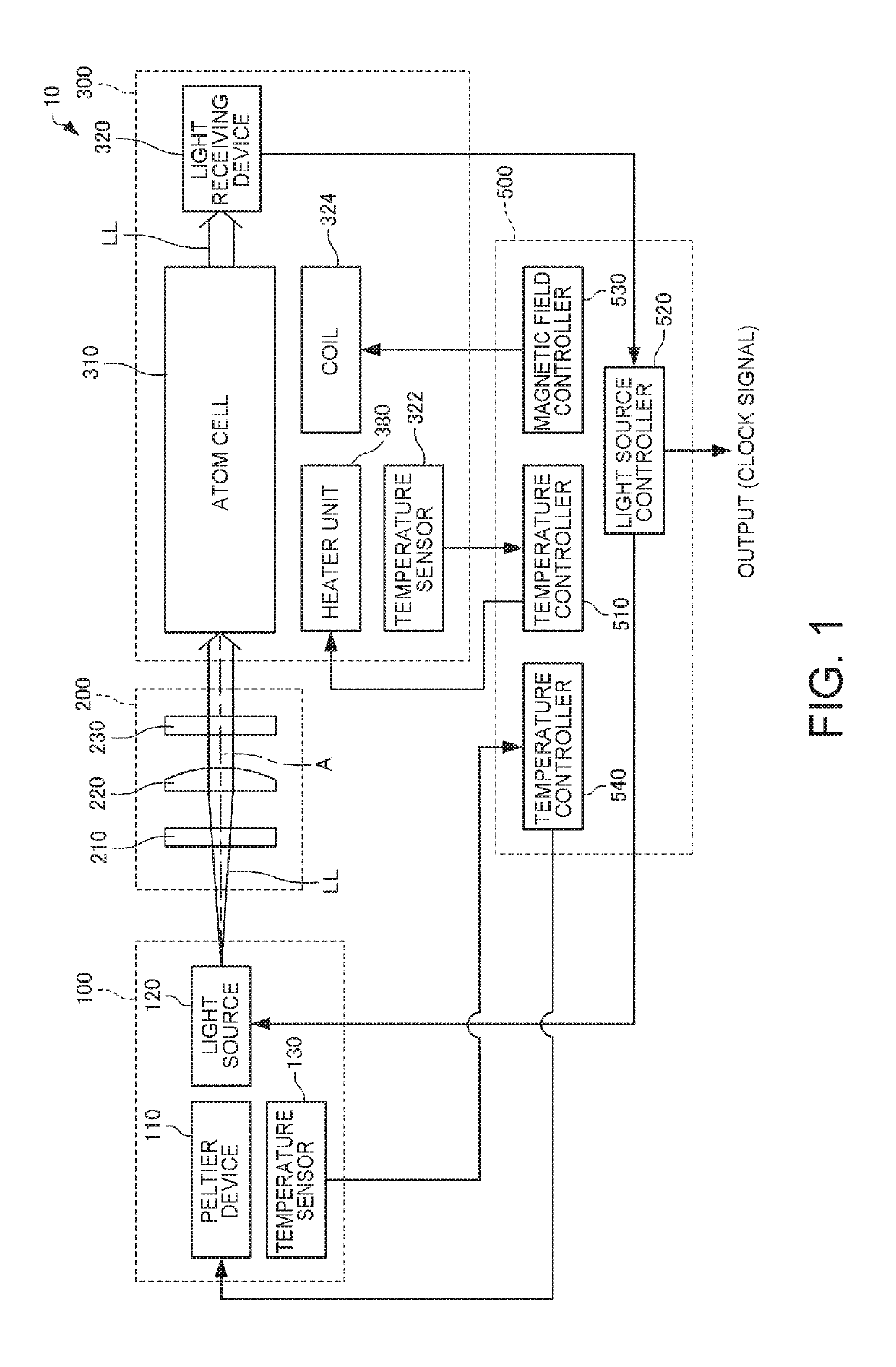
[0043]An atomic oscillator according the present embodiment will first be described with reference to the drawings. FIG. 1 is a schematic view showing an atomic oscillator 10 according to the present embodiment.

[0044]The atomic oscillator 10 is an atomic oscillator using coherent population trapping (CPT) that produces a phenomenon in which when an alkali metal atom is irradiated with two resonance light fluxes having specific different wavelengths at the same time, the two resonance light fluxes are not absorbed by the alkali metal atom but pass therethrough. The phenomenon based on the coherent population trapping ...


PUM


Abstract

An atomic oscillator includes an atom cell that accommodates an alkali metal atom therein, a container that houses the atom cell, a substrate on which the container is disposed, and a thermally insulating mount that is fixed to the substrate and positions the container relative to the substrate.

Description

CROSS-REFERENCE TO RELATED APPLICATIONS[0001]This application claims priority to Japanese Patent Application No. 2017-219401, filed Nov. 14, 2017, the entirety of which is hereby incorporated by reference.BACKGROUND1. Technical Field[0002]The present invention relates to an atomic oscillator and a frequency signal generation system.2. Related Art[0003]As an oscillator having high-precision oscillation characteristics for a long term, there is a known atomic oscillator that oscillates based on energy transition in an alkali metal atom, such as rubidium and cesium.[0004]For example, JP-A-2017-112515 describes an atomic oscillator including an accommodating element that accommodates a gas cell in which a metal atom is sealed and further describes that blocks are disposed at the four corners of the accommodating element and an abutting portion provided as part of a substrate serves as a positioner when the accommodating element is disposed via the blocks.[0005]JP-A-2017-112515 further d...

Claims


Application Information

Patent Timeline
Patent Type & Authority Applications(United States)
IPC IPC(8): H03L7/26H05K9/00H03B17/00H03L1/02
CPCH03L7/26H05K9/0007H03B17/00H03L1/02G04F5/14
Inventor ONISHI, YASUNORIWATANABE, SHUNSUKEHASHI, YUKIHIRO
Owner MICROCHIP TECH INC
Why Eureka
Try Eureka