Worm speed change apparatus and electric power steering apparatus

a technology of electric power steering and speed change, which is applied in the direction of gearing details, transportation and packaging, gearing, etc., can solve the problems of not only the number of components, but also the production cost is reduced, so as to reduce production costs, improve the accuracy of the rotational runout of the worm shaft, and reduce production costs

Inactive Publication Date: 2005-08-09
KOYO SEIKO CO LTD
View PDF14 Cites 0 Cited by
  • Summary
  • Abstract
  • Description
  • Claims
  • Application Information

AI Technical Summary

Benefits of technology

[0010]According to the present invention, the raceway groove is formed directly in the worm shaft. This enables the conventional bearing inner ring to be eliminated. This reduces the worm speed change apparatus in size in the diametral direction of the worm shaft. Further, the reduction not only in the number of component elements, but also in the number of assembling steps, lowers the production cost. Further, the conventional step of pressing the end portion of the worm shaft into the bearing inner ring, can be eliminated, thus further reducing the production cost. Further, the rotational runout precision of the axis of the worm shaft can be improved by reducing the number of component elements.
[0011]The present invention provides, as another preferred phase, an electric power steering apparatus comprising: a steering assistance electric motor; and a worm speed change apparatus for changing the number of rotations of the electric motor, and this worm speed change apparatus comprises: a worm shaft having a pair of end portions; a worm wheel meshed with the worm shaft; a raceway groove formed directly in at least one of the end portions of the worm shaft; a bearing outer ring which is held by a housing and which is opposite to the raceway groove; and a plurality of rolling elements rotatably disposed between the bearing outer ring and the raceway groove, the at least the one of the end portions of the worm shaft being directly received and rotatably supported by the rolling elements. According to the embodiment above-mentioned, a small and economical electric power steering apparatus can be obtained.

Problems solved by technology

Further, the reduction not only in the number of component elements, but also in the number of assembling steps, lowers the production cost.

Method used


Image

  • Worm speed change apparatus and electric power steering apparatus
  • Worm speed change apparatus and electric power steering apparatus
  • Worm speed change apparatus and electric power steering apparatus

Examples


Embodiment Construction

[0016]The following description will discuss preferred embodiments of the present invention with reference to the attached drawings.

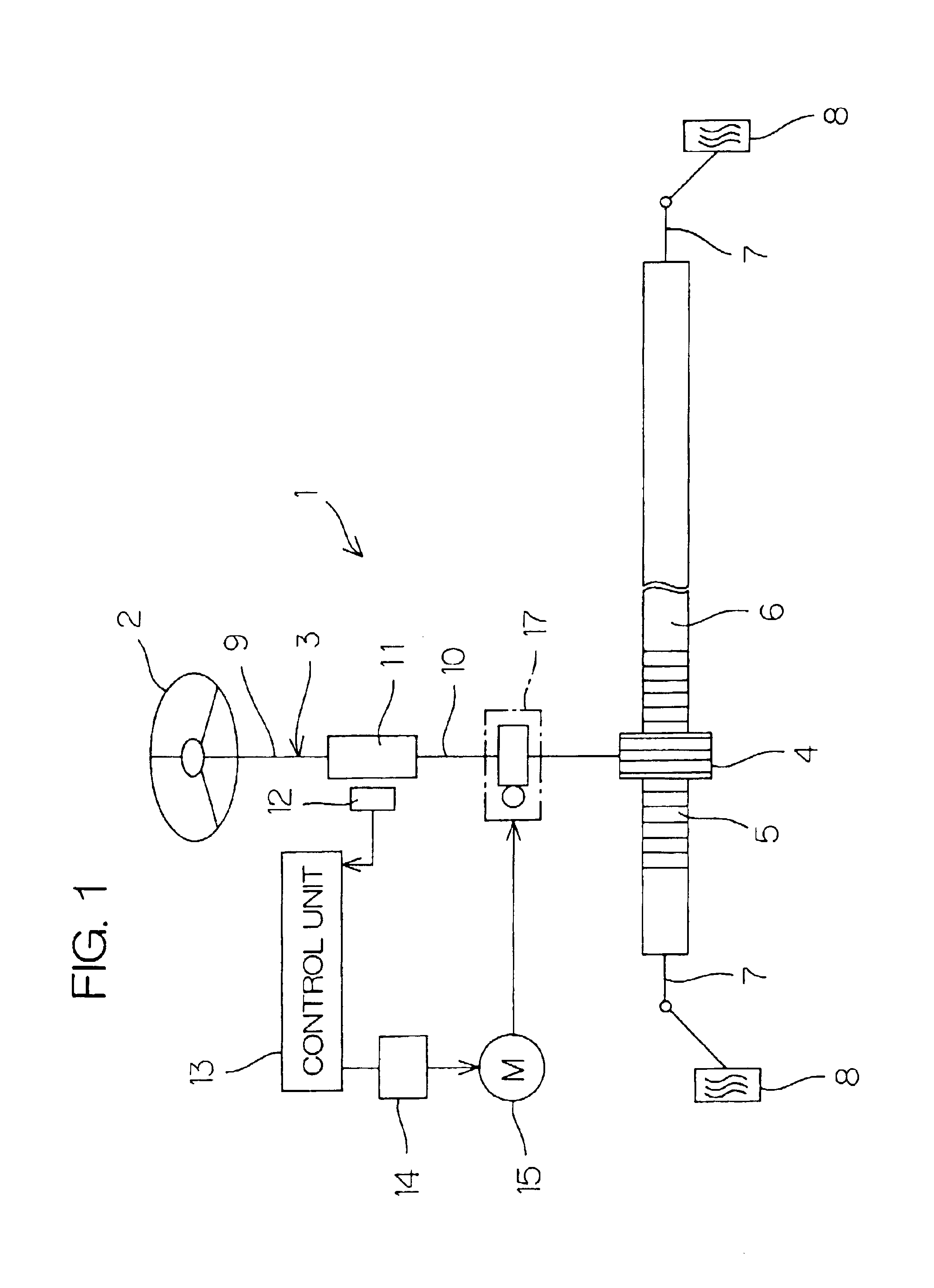
[0017]FIG. 1 is a schematic diagram illustrating the arrangement of an electric power steering apparatus according to an embodiment of the present invention. In FIG. 1, the electric power steering apparatus 1 comprises a steering shaft 3 connected to a steering wheel 2, a pinion 4 disposed at the tip of the steering shaft 3, and a rack shaft 6 which forms a rack 5 meshed with the pinion 4 and which extends transversely of a vehicle body.

[0018]Connected to both ends of the rack shaft 6 are tie rods 7 which are connected to wheels 8 through corresponding knuckle arms (not shown). When the steering wheel 2 is operated to rotate the steering shaft 3, this rotation is converted into a linear motion of the rack shaft 6 in the transverse directions of the vehicle body by the pinion 4 and the rack 5. This steers the wheels 8.

[0019]The steering shaft 3 is divide...


PUM


Abstract

There is provided a worm speed change apparatus comprising a worm shaft and a worm wheel meshed therewith. Rolling elements are rotatably disposed between a raceway groove formed directly in at least one of end portions of the worm shaft, and a bearing outer ring held by a housing. The worm shaft is directly supported by the rolling elements.

Description

CROSS REFERENCE TO RELATED APPLICATION[0001]This Application claims priority benefits under 35 USC Article 119 of Japanese Patent Application Serial No. 2001-307722, the disclosure of which is incorporated herein by reference.BACKGROUND OF THE INVENTION[0002]1. Field of the Invention[0003]The present invention relates to a worm speed change apparatus having a worm shaft and a worm wheel to be meshed therewith, and also relates to an electric power steering apparatus comprising this worm speed change apparatus.[0004]2. Description of Related Art[0005]Generally, an electric power steering apparatus is arranged such that a steering assistance electric motor is reduced in the number of rotations through a speed reducer and that the resulting reduced rotational force is transmitted to a steering mechanism such as a rack-and-pinion mechanism or the like. A worm speed reducer is often used as the above-mentioned speed reducer.[0006]In a worm speed reducer, both ends of the worm shaft meshe...

Claims


Application Information

Patent Timeline
Patent Type & Authority Patents(United States)
IPC IPC(8): B62D5/04F16H1/04F16H1/16F16H57/02
CPCB62D5/0409F16H1/16Y10T74/19828F16H2057/0213Y10T74/18792F16H57/021F16C33/581F16C2361/61
Inventor KITAMI, ETSUROUMAEKAWA, TOMOHIRONAKAJIMA, TERUKAZU
Owner KOYO SEIKO CO LTD
Why Eureka
Try Eureka