Performing in-line service in public cloud

US20190068500A1Active Publication Date: 2019-02-28NICIRA

Image

  • Performing in-line service in public cloud
  • Performing in-line service in public cloud
  • Performing in-line service in public cloud

Examples


Embodiment Construction

[0018]In the following detailed description of the invention, numerous details, examples, and embodiments of the invention are set forth and described. However, it will be clear and apparent to one skilled in the art that the invention is not limited to the embodiments set forth and that the invention may be practiced without some of the specific details and examples discussed.

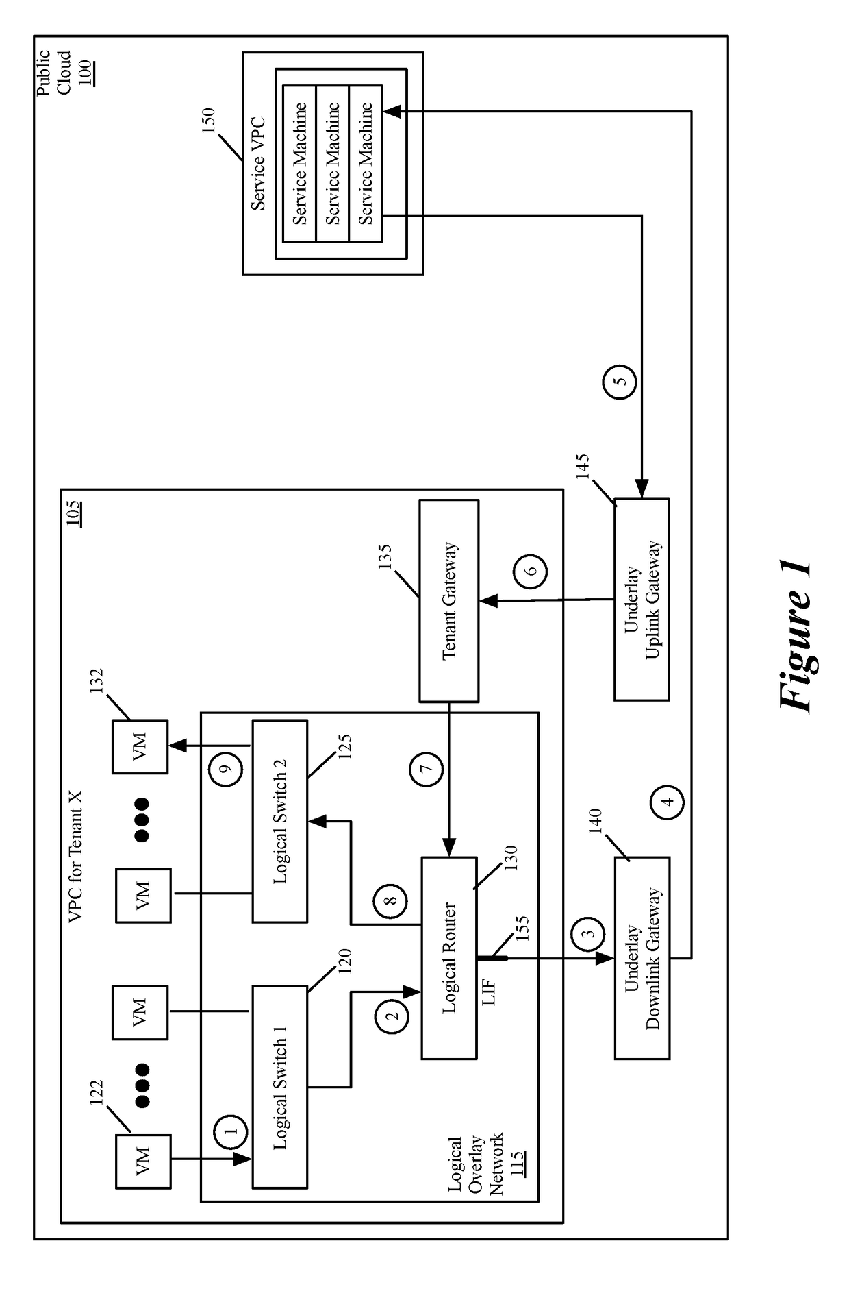
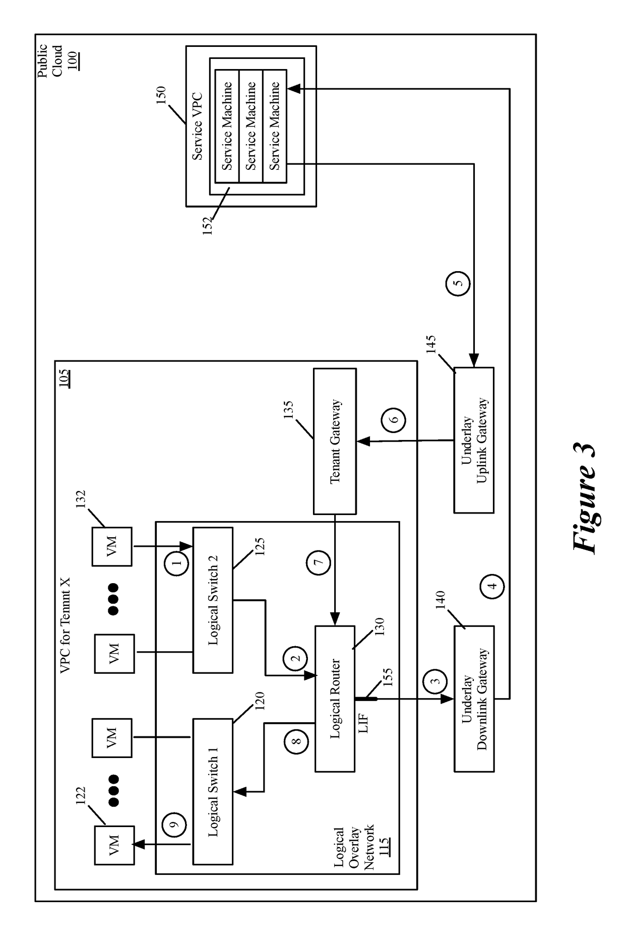
[0019]Some embodiments provide a novel way to insert a service (e.g., a third party service) in the path of a data message flow between two machines (e.g., two VMs, two containers, etc.) in a public cloud environment. For a particular tenant of the public cloud, some embodiments create an overlay logical network with a logical overlay address space. To perform a service on data messages of a flow between two machines, the logical overlay network passes to the public cloud's underlay network the data messages with their destination address (e.g., destination IP addresses) defined in the logical overlay network....


PUM


Abstract

Some embodiments provide a novel way to insert a service (e.g., a third party service) in the path of a data message flow, between two machines (e.g., two VMs, two containers, etc.) in a public cloud environment. For a particular tenant of the public cloud, some embodiments create an overlay logical network with a logical overlay address space. To perform a service on data messages of a flow between two machines, the logical overlay network passes to the public cloud's underlay network the data messages with their destination address (e.g., destination IP addresses) defined in the logical overlay network. The underlay network (e.g., an underlay default downlink gateway) is configured to pass data messages with such destination addresses (e.g., with logical overlay destination addresses) to a set of one or more service machines. The underlay network (e.g., an underlay default uplink gateway) is also configured to pass to the particular tenant's public cloud gateway the processed data messages that are received from the service machine set and that are addressed to logical overlay destination addresses. The tenant's public cloud gateway is configured to forward such data messages to a logical forwarding element of the logical network, which then handles the forwarding of the data messages to the correct destination machine.

Description

BACKGROUND[0001]In private clouds today, numerous vendors provide specialized services, such as Deep Packet Inspection, Firewall, etc. In private datacenters, the administrators typically deploy such specialized services in the path of traffic that needs the service. With the proliferation of public cloud, these vendors also offer virtual appliances and service virtual machines (service VMs) that can be licensed and deployed in public cloud environments. For example, Palo Alto Networks makes its firewall available as a virtual appliance in the Amazon Web Services (AWS) marketplace.[0002]Such appliances are mostly deployed for traffic that enters and leaves the virtual public cloud (VPC) in the datacenter, and are thus deployed facing the Internet Gateway. However, the public cloud tenants also want to route the traffic between subsets of endpoints within the virtual datacenter through the service appliance of third party vendors. Currently, this is not possible as cloud providers do...

Claims


Application Information

Patent Timeline
28 Feb 2019
Publication
US20190068500A1
IPC
H04L12/741; H04L12/715; H04L12/931; H04L12/66; H04L12/24; H04L45/74
CPC
H04L45/745; H04L45/64; H04L49/354; H04L49/70; H04L12/66; H04L41/0803; H04L12/4641; H04L45/00
Inventors
HIRA, MUKESH