Speaker diaphragm
a diaphragm and speaker technology, applied in the direction of diaphragm construction, transducer diaphragm, electromechanical transducer, etc., can solve the problems of insufficient diaphragm strength or underdamping, and achieve the reduction of frequency peaks and valleys, the overall strength of the diaphragm, and the effect of increasing the frequency
- Summary
- Abstract
- Description
- Claims
- Application Information
AI Technical Summary
Benefits of technology
Problems solved by technology
Method used
Image
Examples
embodiment 1
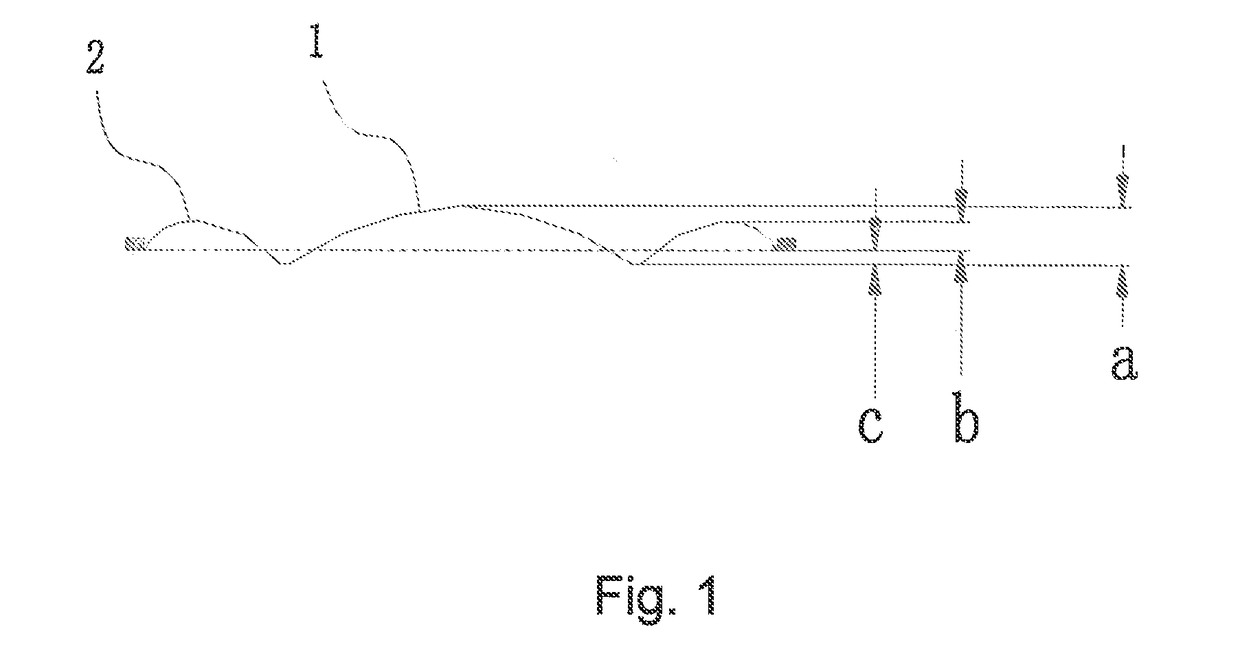
[0026]As shown in FIG. 1, a speaker diaphragm of the invention is composed of a dome portion 1 located in the center and a circle of outer arc portion 2 connected to the circumferential outer side of the dome portion.
[0027]An outer diameter of the diaphragm is 38.9 mm.
[0028]The dome portion 1 has a dome height a of 3.0 mm. The dome height a refers to a difference in height between the highest point in the middle of the dome portion 1 and the bottom edge of the dome portion 1.
[0029]The outer arc portion 2 has an arc top height b of 1.6 mm. The arc top height b refers to a difference in height between the highest point of the arc top of the outer arc portion 2 and the bottom edge of the outer side of the outer arc portion 2.
[0030]An effective height c between the dome portion 1 and the outer are portion 2 is 0.8 mm. The effective height c refers to a difference in height between the bottom edge of the outer side of the outer are portion 2 and the bottom edge of the dome portion 1.
[003...
embodiment 2
[0032]As shown in FIG. 1, a speaker diaphragm of the invention is composed of a dome portion 1 located in the center and a circle of outer are portion 2 connected to the circumferential outer side of the dome portion 1.
[0033]An outer diameter of the diaphragm is 39.95 mm.
[0034]The dome portion 1 has a dome height a of 3.4 mm.
[0035]The outer arc portion 2 has an arc top height b of 1.8 mm.
[0036]An effective height c between the dome portion 1 and the outer arc portion 2 is 1.0 mm.
embodiment 3
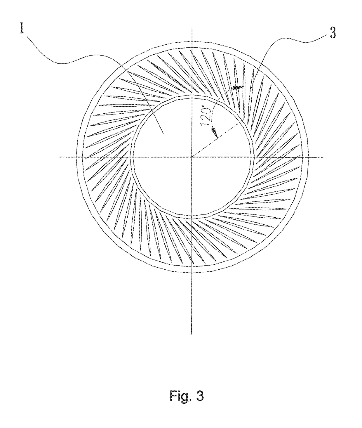
[0037]As shown in FIG. 3, in order to further improve the frequency response curve of the diaphragm, the present embodiment is improved on the basis of Embodiment 1 or Embodiment 2:
[0038]the surface of the outer arc portion 2 is also provided with a circle of array of annular concave pattern 3 taking the center of the dome portion 1 as a circle center, the concave patterns 3 being elongated.
[0039]As shown in FIG. 4, an included angle between a connection line of the root of any of the concave patterns 3 and the center of the dome portion 1 and an axial centerline of the concave pattern 3 is 120 degrees.
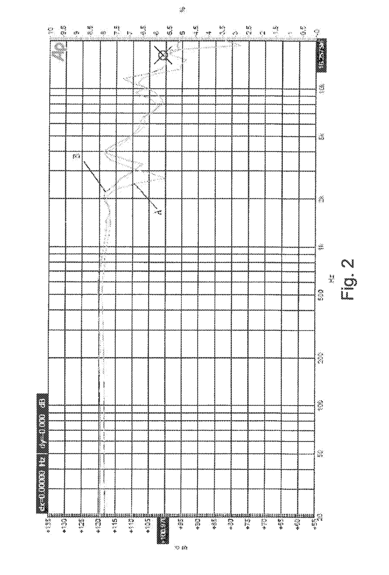
[0040]The diaphragm is subjected to a frequency response testing comparison before and after the inclination angles of the concave patterns 3 are adjusted. The testing results as shown in FIG. 5.
[0041]Optionally, an included angle between a connection line of the root of the concave pattern 3 and the center of the dome portion 1 and the axial centerline of the concave pattern 3 is 120...
PUM
 Abstract
Description
Claims
Application Information
 - R&D
- Intellectual Property
- Life Sciences
- Materials
- Tech Scout
- Unparalleled Data Quality
- Higher Quality Content
- 60% Fewer Hallucinations
Browse by: Latest US Patents, China's latest patents, Technical Efficacy Thesaurus, Application Domain, Technology Topic, Popular Technical Reports.
© 2025 PatSnap. All rights reserved.Legal|Privacy policy|Modern Slavery Act Transparency Statement|Sitemap|About US| Contact US: help@patsnap.com


