Luminous necklace structure

a technology of luminous necklaces and wires, which is applied in the field of luminous ornaments, can solve the problems of short service life of luminous necklaces, waste to a certain extent, and limited connection strength between luminophors and wires, and achieve the effect of convenient use and longer service li

Active Publication Date: 2019-03-07
ACE GIFT&CRAFTNINGBOCO LTD
View PDF7 Cites 18 Cited by
  • Summary
  • Abstract
  • Description
  • Claims
  • Application Information

AI Technical Summary

Benefits of technology

[0006]In view of the above-mentioned problems in the prior art, the objective of the present invention discloses a lum

Problems solved by technology

The luminous necklace of this structure has the following technical problems: 1. the luminophor and the light shade are connected in the only one traditional way which is too less selectable so that it cannot realize the provision and non-provision of lights in the light shades; 2. the luminophor is a consumable and cannot be fully protect

Method used


Image

  • Luminous necklace structure
  • Luminous necklace structure
  • Luminous necklace structure

Examples


embodiment 1

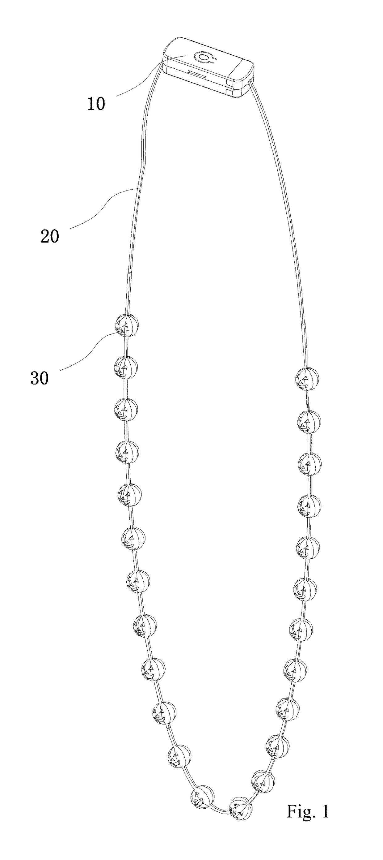
[0066]As shown in FIG. 1, the pendant is a light shade 30 made of a plastic material and the light shade 30 is electrically connected with a luminophor capable of being mounted on the chain rope 20, and the light shade 30 is fixed to the chain rope 20 and the luminophor via an injection molding process, which enhances the assembling efficiency as well as the connecting strength between the chain rope 20 and the light shade 30; additionally, the light shade 30 wraps the entire luminophor inside, which also enhances the strength of the connection between the luminophor and the chain 20 and protects the luminophor as well, thus prolonging the service life of the entire necklace structure.

[0067]It shall be noted that the light shade 30 can also be directly molded onto the portion of the chain rope 20 where the luminophor is not mounted, so as to form a non-luminous light shade 30 on the chain rope 20; in this way, the luminous light shade 30 is interlaced with the non-luminous light sha...

embodiment 2

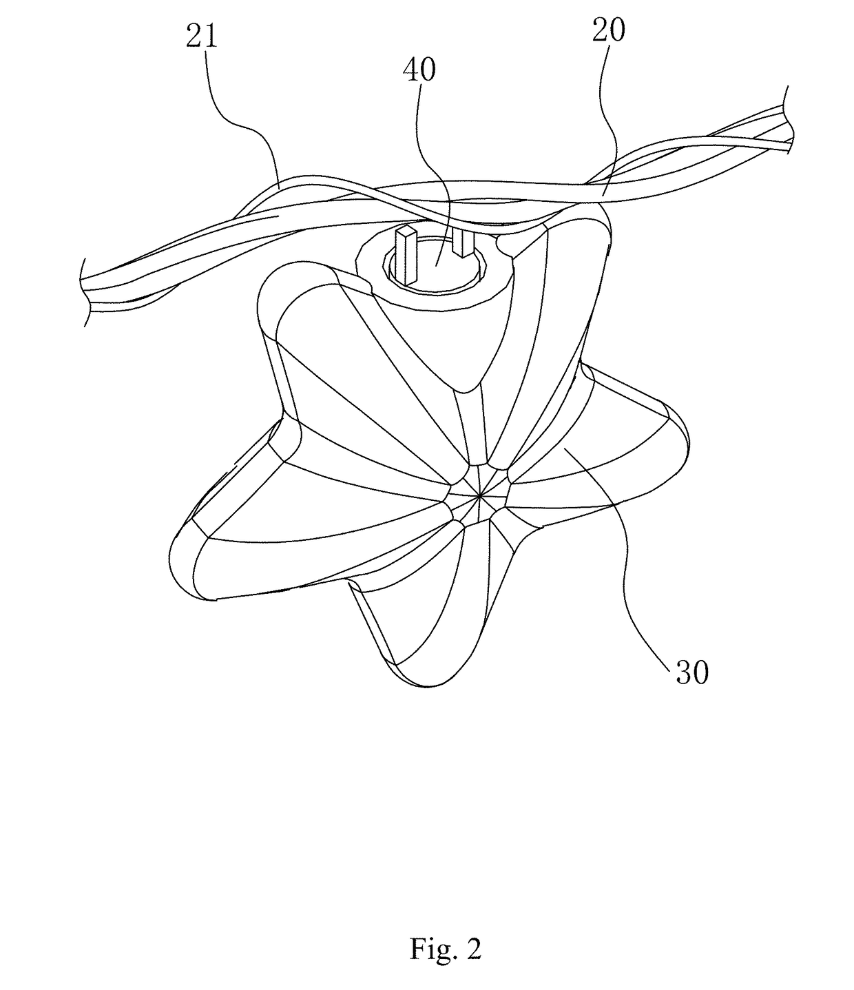
[0070]As shown in FIG. 2, the pendant is a light shade made of a plastic material and the light shade is provided with a connecting hole, and a luminophor 40 electrically connected with the chain rope 20 can be fixed into the connecting hole; the luminophor 40 needs to be directly connected with the chain rope 20 to make itself luminous, and the luminophor 40 is directly fixed into the connecting hole of the light shade, that is to say, the connection between the light shade and the chain rope 20 is realized through the luminophor 40; the connection between the luminophor 40 and the light shade makes the close matching of the luminophor 40 and the connecting hole, or after the luminophor 40 extends into the connecting hole, the glues for bonding can be injected into the connecting hole so as to fix the luminophor 40 into the connecting hole; this kind of connecting structure is simple and easy for assembly and saves production costs.

[0071]Preferably, the chain rope 20 comprises two ...

embodiment 3

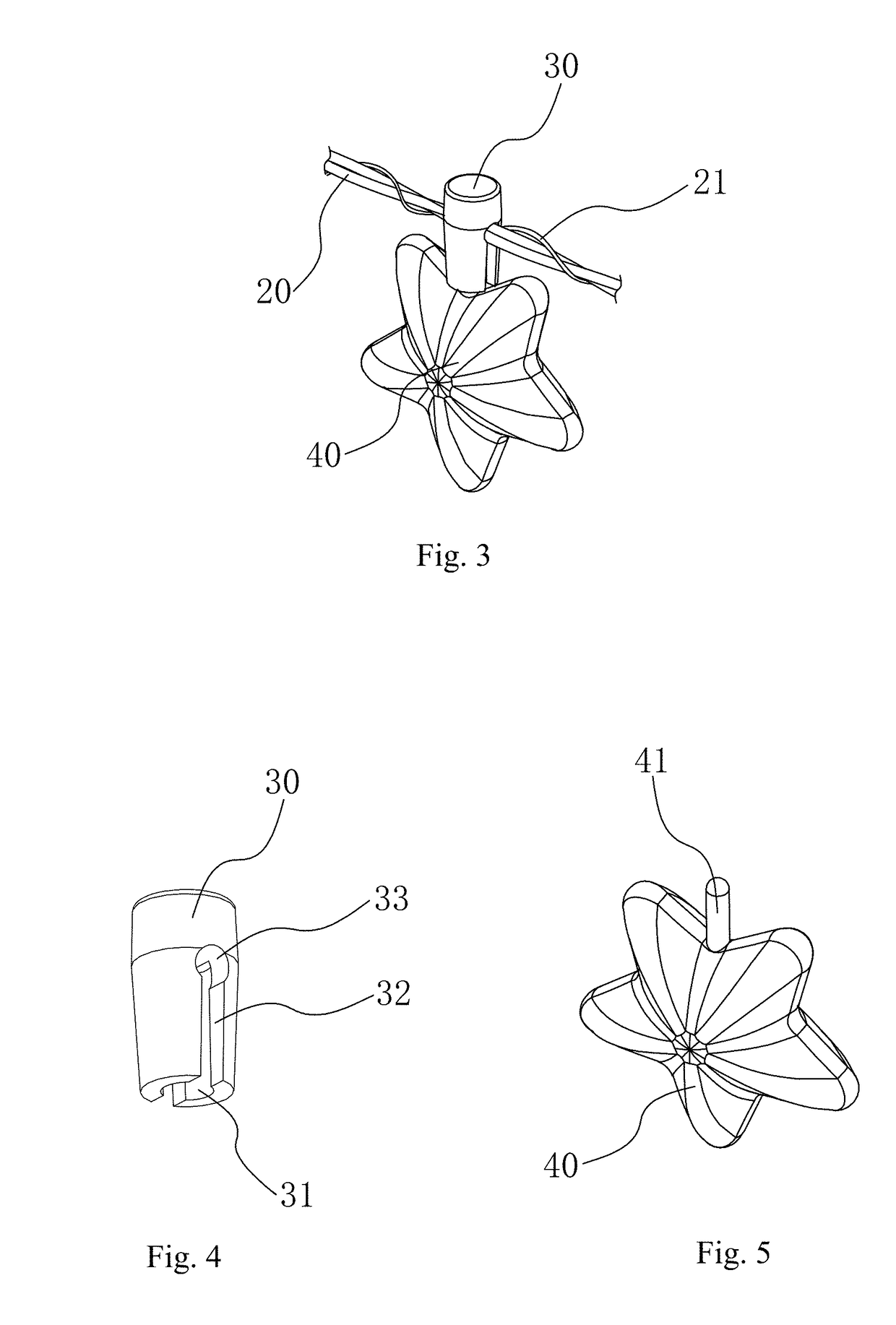
[0073]As shown in FIG. 3-FIG. 5, the pendant comprises a light holder 30 and a light shade 40; wherein being basically of a column structure and made of a plastic material, the light holder 30 is connected with the chain rope 20, and being of a pervious structure of all kinds of shapes, structures and colors, the light shade 40 is also of a plastic structure; the light holder 30 is provided with an insertion hole 31 on one end and the light shade 40 is provided with an insertion rod 41, wherein the insertion rod 41 is inserted into and closely matched with the insertion hole 31, which realizes the removable connection between the light holder 30 and the light shade 40 through the matching of the insertion rod 41 and the insertion hole 31, thus making the assembly of the light holder 30 and the light shade 40 more convenient.

[0074]As shown in FIG. 4, the light holder 30 is provided on one end with a clip groove 32 which traverses the light holder 30, and extends from one end of the l...


PUM


Abstract

Disclosed is a luminous necklace structure. The present invention adopts the following technical solution: A luminous necklace structure, comprising a battery case; a chain rope with both ends connected with the battery case; at least one pendant connected with the chain rope; so that the battery case can supply power to the chain rope and make the pendant luminous. The chain rope comprises two conductive wires which are fixedly connected in parallel. The battery case comprises a casing and a power supply assembly provided in the casing, with two ends of the two conductive wires connected to the casing and the conductive wires electrically connected to the power supply assembly.

Description

CROSS REFERENCE TO RELATED APPLICATION[0001]This application is a Continuation-in-Part of U.S. patent application Ser. No. 15 / 438,824 entitled A LUMINOUS NECKLACE STRUCTURE filed Feb. 22, 2017, which application claims priority to Chinese Patent Application No. 201610796312.7 filed on Aug. 31, 2016, Chinese Patent Application No. 201611206968.5 filed on Dec. 23, 2016 and Chinese Patent Application No. 201620736383.3 filed on Jul. 11, 2016, the entire contents of which are incorporated by reference herein.BACKGROUND OF THE INVENTION1. Technical Field[0002]The present invention belongs to the technical field of luminous ornaments, and more especially, to a luminous necklace structure.2. Description of Related Art[0003]The luminous ornaments are under the category of ornaments with a special structure in the field of ornaments. The combination of the light and ornaments through the provision of batteries and luminophors into the ornaments makes the ornaments more widely used and more p...

Claims


Application Information

Patent Timeline
IPC IPC(8): A44C15/00A44C11/00F21V23/02F21V23/00F21V3/08
CPCA44C15/0015A44C11/00A44C15/005F21V23/023F21V23/001F21V3/08F21W2121/06F21S4/10F21W2121/00F21V33/0008F21S9/02
Inventor QIN, YANBEI
Owner ACE GIFT&CRAFTNINGBOCO LTD
Why Eureka
Try Eureka