
Radiation therapy interactive planning

a radiation therapy and interactive technology, applied in radiation therapy, radiation therapy, x-ray/gamma-ray/particle irradiation therapy, etc., can solve the problems of difficult to ascertain the progress of the optimizer toward an acceptable solution, complex and time-consuming planning task, and contradictions in the optimization process

Active Publication Date: 2019-03-07
KONINKLJIJKE PHILIPS NV
View PDF2 Cites 19 Cited by
  • Summary
  • Abstract
  • Description
  • Claims
  • Application Information

AI Technical Summary

Benefits of technology

The technical effects of the patent text have addressed the problems of the prior art and provided a solution to these issues.

Problems solved by technology

However, planning is a complex and time consuming task especially for IMRT Simultaneous Integrated Boost cases.
Adding objectives in the inverse planning optimization can add interactions with other objectives, which can cause contradictions in the optimization process.
Moreover, progress of the optimizer toward an acceptable solution can be difficult to ascertain.
With different dose objectives according to target and OAR structures and parameters for each, set-up and control of the optimizer alone becomes a complex task.
However, the iso-contours make it difficult to understand and identify overall progress and contradictions interpreted throughout the iso-contours over an entire planning volume that the healthcare practitioner must navigate.
In addition, it is difficult to compare development of a previously optimized plan that has similarities with a current plan to aid in deciding or initializing optimization parameters.

Method used


Image

  • Radiation therapy interactive planning
  • Radiation therapy interactive planning
  • Radiation therapy interactive planning

Examples


Embodiment Construction

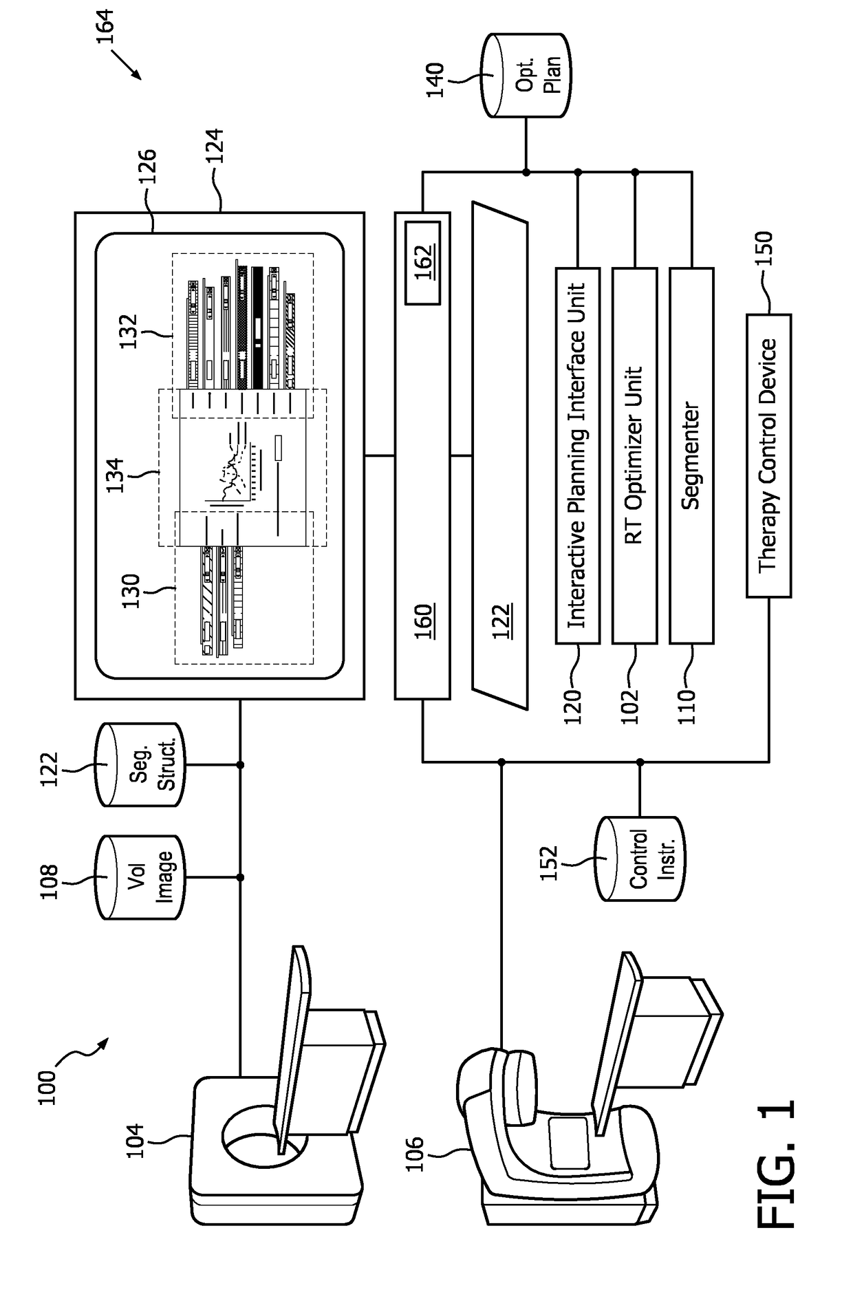
[0020]Initially referring to FIG. 1, an example RT system 100 with interactive control of an optimizer unit 102 in connection with an imaging device 104 and a radiation delivery device 106 is schematically illustrated. The imaging device 104 includes a scanner of one or more modalities such as an X-ray Computed Tomography (CT) scanner, Magnetic Resonance Imaging (MRI) scanner, a Positron Emission Tomography (PET) scanner, a Single Proton Emission Computed Tomography (SPECT) scanner, combinations, hybrids and the like, which generates a volumetric image 108 of a region of interest (ROI) of a subject used to plan the radiation therapy. The volumetric planning image 108 includes at least a three-dimensional (3D) image, e.g. volume image constructed from 2D slices, 3D image, 4D image, etc. The volumetric planning image 108 can be received directly from the imaging device 104 or stored in an electronic memory, such as a Picture Archiving and Communication System (PACS), a Radiology Infor...


PUM


Abstract

A radiation therapy system (100) includes a radiation therapy (RT) optimizer unit (102) and an interactive planning interface unit (120). The RT optimizer unit (102) receives at least one target structure and at least one organ-at-risk (OAR) structure segmented from a volumetric image (108), and generates an optimized RT plan (140) based on dose objectives (200-204, 210-222, 320), at least one dose objective of the dose objectives corresponding to each of the at least one target structure (210-222) and the at least one OAR structure (200-204). The optimized RT plan includes a planned radiation dose for each voxel of the volumetric image using external beam radiation therapy, wherein the RT optimizer unit operates iteratively. The interactive planning interface unit (120) interactively controls each of the dose objectives through controls (300) displayed on a single display (126) of a display device (124), operates the RT optimizer unit to iteratively compute the planned radiation dose according to the controls, and provide visual feedback (310, 134) on the single display according to progress of the RT optimizer unit after each trial.

Description

FIELD OF THE INVENTION[0001]The following generally relates to external beam radiation therapy, and is described with particular application to inverse planning optimization techniques, such as Intensity Modulate Radiation Therapy (IMRT), Intensity Modulated Proton Therapy (IMPT) and / or Volumetric Modulated Arc Therapy (VMAT) radiation therapy planning.BACKGROUND OF THE INVENTION[0002]IMRT, IMPT and / or VMAT radiation therapy techniques deliver high doses to target areas, such as cancerous growth, to destroy or control diseased tissues in the target area. Dose goals are identified by a healthcare practitioner based on one or more volumetric planning images, e.g. an X-ray Computed Tomography (CT) image. Based on the dose goals an optimizer is used to plan the orientation, duration, shape and / or intensity of beams of external radiation to the target areas. The inversely planned external beams according to dose objectives is different from other radiation therapy direct planning methods...

Claims


Application Information

Patent Timeline
Patent Type & Authority Applications(United States)
IPC IPC(8): A61N5/10
CPCA61N5/1031A61N5/1048A61N5/1039A61N2005/1074A61N5/1049A61N2005/1055A61N2005/1061A61N2005/1052A61N2005/1087A61N5/103
Inventor JOE ANTO, GIPSONKRISHNAIYER RAMAN, SIVARAMAKRISHNANRANGANATHAN, VAITHEESWARAN
Owner KONINKLJIJKE PHILIPS NV
Learn More