
Display device

a display device and display technology, applied in the field of display devices, can solve the problems of difficult to sense an accurate bending degree, and small change in the resistance of the bending sensor, so as to reduce the size of the display device's bezel area

Active Publication Date: 2019-03-07
LG DISPLAY CO LTD
View PDF0 Cites 27 Cited by
  • Summary
  • Abstract
  • Description
  • Claims
  • Application Information

AI Technical Summary

Benefits of technology

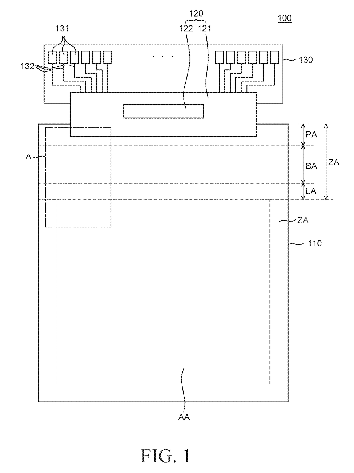
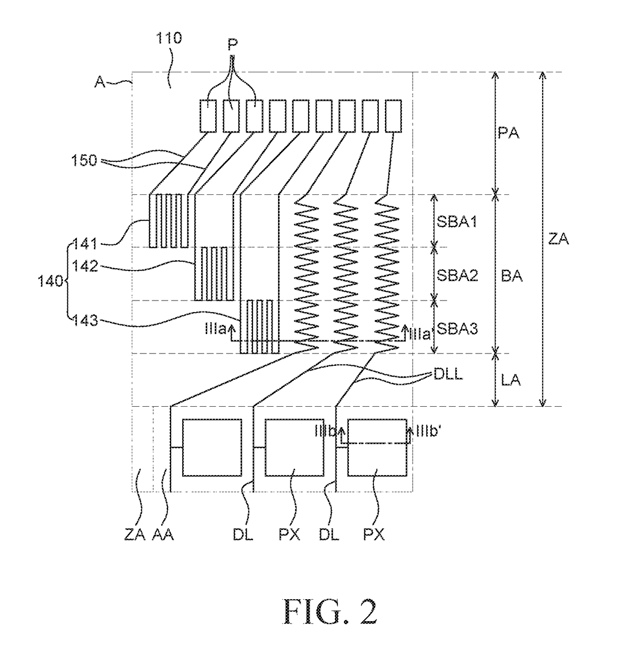
This patent describes a display device that includes a flexible substrate with bending sensing patterns that detect pressure on the device. The device also has a temperature monitoring pattern that detects changes in the device's temperature. These patterns are placed in a bezel area that surrounds the display area, which makes it easier to identify areas that may have cracks or may not be bent correctly. The inventors also discovered that the density of the bending sensing patterns in areas with a small radius of curvature is larger than the density of the bending sensing patterns in areas with a large radius of curvature, which allows for more precise sensing of the bending degree. Additionally, the inventors found that the size of the bezel area can be reduced by sharing pads between the temperature monitoring pattern and the bending sensing patterns. The temperature monitoring pattern can also be shaped differently from the bending monitoring pattern to further reduce the size of the bezel area. Overall, this patent aims to provide a display device with improved bending sensing and temperature monitoring capabilities.

Problems solved by technology

However, when one bending sensor is disposed in the entire bending area, it is difficult to sense a bending degree for every each position of the bending area.
Further, since the bending sensor is disposed in the entire bending area, a change in the resistance of the bending sensor is small.
Therefore, it is difficult to sense an accurate bending degree.

Method used


Image

  • Display device
  • Display device
  • Display device

Examples


Embodiment Construction

[0039]Advantages and characteristics of the present disclosure and a method of achieving the advantages and characteristics will be clear by referring to example embodiments described below in detail together with the accompanying drawings. However, the present disclosure is not limited to the example embodiments disclosed herein but will be implemented in various forms. The example embodiments are provided by way of example only so that a person of ordinary skill in the art can fully understand the disclosures of the present disclosure and the scope of the present disclosure. Therefore, the present disclosure will be defined only by the scope of the appended claims.

[0040]The shapes, sizes, ratios, angles, numbers, and the like illustrated in the accompanying drawings for describing the example embodiments of the present disclosure are merely examples, and the present disclosure is not limited thereto. Like reference numerals generally denote like elements throughout the specificati...


PUM


Abstract

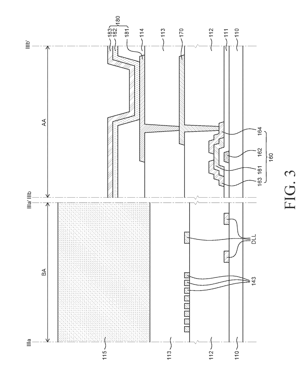
Discussed is a display device including a flexible substrate having an active area, a bezel area enclosing the active area, and a bending area defined in at least a part of the active area and the bezel area; and a plurality of bending sensing patterns disposed in the bending area, in which the bending area includes a plurality of sub bending areas and the plurality of bending sensing patterns is disposed in different areas of the plurality of sub bending areas. Therefore, the bending degree of each sub bending area included in the bending area can be independently sensed.

Description

CROSS-REFERENCE TO RELATED APPLICATIONS[0001]This application claims the priority benefit of Korean Patent Application No. 10-2017-0113498 filed on Sep. 5, 2017 and Korean Patent Application No. 10-2018-0093832 filed on Aug. 10, 2018, both filed in the Korean Intellectual Property Office, the disclosure of each which is incorporated herein by reference in its entirety.BACKGROUND OF THE INVENTIONField of the Invention[0002]The present disclosure relates to a display device, and more particularly, to a display device in which a plurality of bending sensing patterns which senses bending of the display device is disposed in different areas in a bending area of the display device.Description of the Related Art[0003]Recently, a flexible display device is manufactured by forming a display unit and a wiring line on a flexible substrate formed of a material such as plastic. Thus, the flexible display is capable of displaying images even though the display device is bent like a paper, and is ...

Claims


Application Information

Patent Timeline
IPC IPC(8): H01L27/32H01L51/00G01B7/16G01K7/16
CPCH01L27/3225H01L51/0097H01L27/3276H01L27/3262H01L27/3258G01B7/16G01K7/16H01L2251/5338G01B7/18G09F9/301G01K13/00G01B7/287Y02E10/549H10K59/123H10K59/124H10K59/131H10K77/111H10K2102/311H10K59/00H10K59/1213
Inventor KIM, MINKYUHAN, MINJIJANG, SUNGHYUNLEE, BOTAEK
Owner LG DISPLAY CO LTD
Learn More