Touch panel and touch display device

A technology of a touch display device and a touch panel, which is applied to instruments, electrical digital data processing, and the input/output process of data processing, etc., and can solve problems such as a large frame size of a touch panel, achieve a small frame size, and avoid signal Effects of interference and wiring space reduction

Inactive Publication Date: 2018-08-24
INTERFACE TECH CHENGDU CO LTD +2
View PDF9 Cites 9 Cited by
  • Summary
  • Abstract
  • Description
  • Claims
  • Application Information

AI Technical Summary

Problems solved by technology

[0003] However, since the touch driving electrode traces (Tx line) and the touch sensing electrode traces (Rx line) are signals of different attributes, the voltage intensity is ten times worse, so usually touch The parallel adjacent places of driving electrode traces (Txline) and touch sensing electrode traces (Rx line) must be separated by a thicker ground wire (GND). The bezel size of the touch panel is large

Method used


Image

  • Touch panel and touch display device
  • Touch panel and touch display device
  • Touch panel and touch display device

Examples


no. 1 example

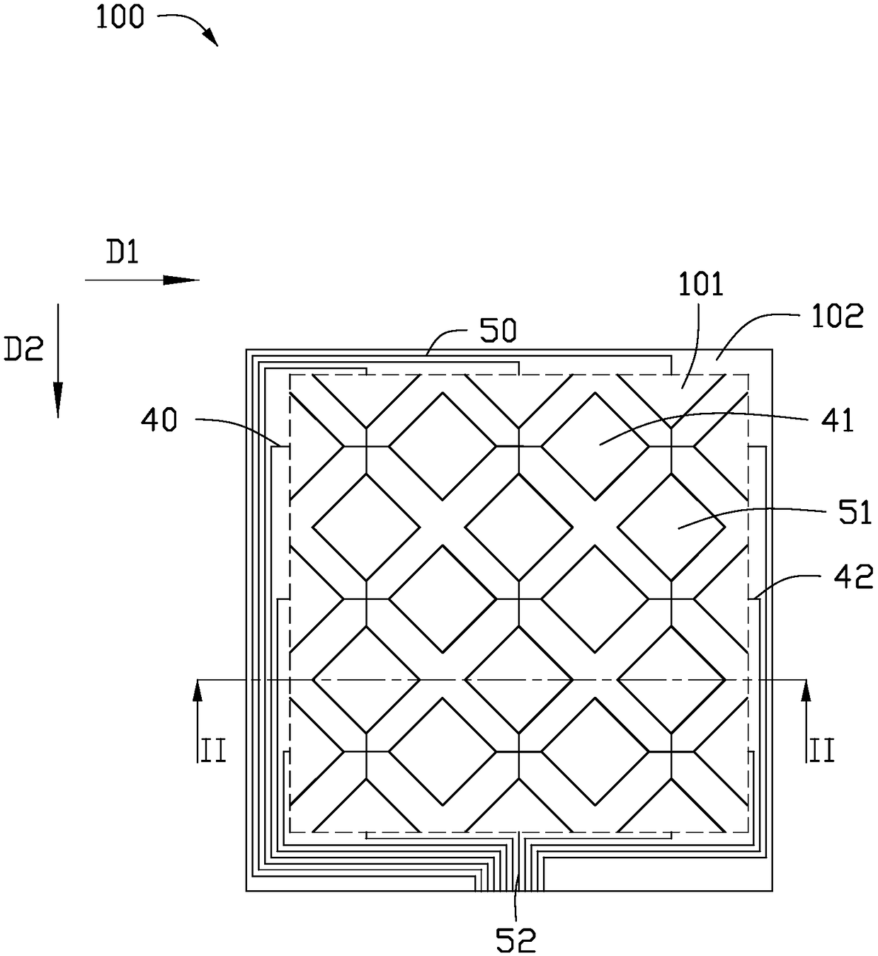
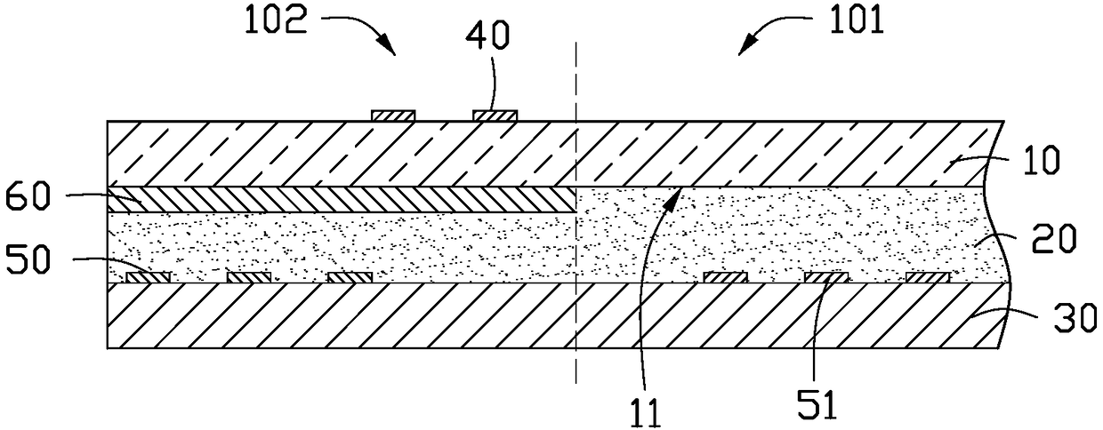
[0022] figure 1 It is a schematic plan view of the touch panel according to the first embodiment of the present invention. Such as figure 1 As shown, the touch panel 100 defines a touch area 101 and a wiring area 102 surrounding the touch area 101, and the touch area 101 is provided with a plurality of first electrodes 41 and a plurality of second electrodes 51 , the routing area 102 is provided with a plurality of first routings 40 and a plurality of second routings 50, the plurality of first routings 40 are electrically connected to the first electrodes 41, and the plurality of second routings The wiring 50 is electrically connected to the second electrode 51 .

[0023] Specifically, the plurality of first electrodes 41 are arranged in multiple rows along the first direction D1, and the plurality of first electrodes 41 in each row are electrically connected in turn to form a first electrode string; the plurality of second electrodes 51 are arranged in multiple rows along ...

no. 2 example

[0035] Figure 4 It is a schematic plan view of the touch panel according to the second embodiment of the present invention. Such as image 3 As shown, the touch panel 200 provided in this embodiment is basically the same as the touch panel 100 in the first embodiment, and the touch panel 200 also defines a touch area 101 and a wiring area surrounding the touch area 101 102, the touch area 101 is provided with a first electrode 41 and a second electrode 51, and the wiring area 102 is provided with a plurality of first wiring 40 and a plurality of second wiring 50, and the plurality of first The traces 40 are electrically connected to the first electrodes 41 , and the plurality of second traces 50 are electrically connected to the second electrodes 51 . The touch area 101 is roughly rectangular, and the wiring area 102 includes a left area and a right area located on the left and right sides of the touch area 101 and an upper area and a lower area located on the upper and low...

no. 3 example

[0043] Figure 7 It is a schematic plan view of a touch panel 300 according to a third embodiment of the present invention. Such as Figure 7 As shown, the touch panel 300 provided in this embodiment is basically the same as the touch panel 200 in the second embodiment, and the touch panel 300 also defines a touch area 101 and a wiring area surrounding the touch area 101 102, the touch area 101 is provided with a first electrode 41 and a second electrode 51, and the wiring area 102 is provided with a plurality of first wiring 40 and a plurality of second wiring 50, and the plurality of first The traces 40 are electrically connected to the first electrodes 41 , and the plurality of second traces 50 are electrically connected to the second electrodes 51 . The touch area 101 is roughly rectangular, and the wiring area 102 includes a left area and a right area located on the left and right sides of the touch area 101 and an upper area and a lower area located on the upper and lo...


PUM


Abstract

The invention discloses a touch panel, which defines a touch area and a routing area which surrounds the touch area, wherein the touch area is provided with a plurality of first electrodes and a plurality of second electrodes; the routing area is provided with a plurality of first routes and a plurality of second routes; the plurality of first routes are electrically connected with the first electrodes; and the plurality of second electrodes are electrically connected with the second electrodes. The touch panel also comprises a first ground lead which is mutually insulated from the plurality of first routes and the plurality of second routes; the plurality of first routes, the first ground lead and the plurality of second routes are overlapped from top to bottom in sequence; and the plurality of first routes and the plurality of second routes are independently overlapped with the first ground lead. By use of the touch panel, the plurality of first routes and the plurality of second routes are all overlapped to the first ground lead, signal interference among the routes is avoided, the size of a routing area is reduced, and therefore, the border size of the touch panel can be narrowed.

Description

technical field [0001] The present invention relates to the field of touch technology, in particular to a touch panel and a touch display device. Background technique [0002] As an input medium, a touch display device is currently the simplest and most convenient way of human-computer interaction. Therefore, the touch display device is more and more applied to various electronic products. In response to market demand for lightness, thinness, and aesthetics, the design of narrow bezels will be one of the trends. [0003] However, since the touch driving electrode traces (Tx line) and the touch sensing electrode traces (Rx line) are signals of different attributes, the voltage intensity is ten times worse, so usually touch The parallel adjacent places of driving electrode traces (Txline) and touch sensing electrode traces (Rx line) must be separated by a thicker ground wire (GND). The bezel size of the touch panel is large. Contents of the invention [0004] In view of t...

Claims


Application Information

Patent Timeline
Patent Type & Authority Applications(China)
IPC IPC(8): G06F3/044G06F3/041
CPCG06F3/0412G06F3/044
Inventor 李炫运
Owner INTERFACE TECH CHENGDU CO LTD
Why Eureka
Try Eureka