Wireless earphone and charging case

a charging case and earphone technology, applied in the direction of charging attachments/accumulators, loudspeakers, transportation and packaging, etc., can solve the problems of user's inability to listen to music or view content, and the sound signal of an electronic device cannot be reproduced, so as to reduce the number of terminals required, suppress the discharging of batteries contained, and increase the usage time of batteries

Active Publication Date: 2019-03-07
CRESYN
View PDF6 Cites 31 Cited by
  • Summary
  • Abstract
  • Description
  • Claims
  • Application Information

AI Technical Summary

Benefits of technology

[0009]A first object of the present invention is to output sound signals, received by wireless earphones, to a speaker provided in a charging case when the wireless earphones are connected to the charging case and charged with power, thereby enabling music to be listened to or content, such as a movie, a drama, or the like, to be viewed during the charging of the wireless earphones.
[0010]A second object of the present invention is to provide a charging case with its own battery, thereby enabling wireless earphones to be charged with power while being carried.
[0011]A third object of the present invention is to maximally suppress the discharging of batteries contained in wireless earphones and a charging case, thereby increasing the usage time of the batteries.
[0012]A fourth object of the present invention is to reduce the number of terminals required for the electrical connection between wireless earphones and a charging case and the detection of the connection while maintaining the electrical connectivity and coupling between the wireless earphone and the charging case.

Problems solved by technology

A conventional wireless earphone system, such as that described above, is problematic in that a user cannot listen to music or view content, such as a movie, a drama, or the like, during the charging of the wireless earphones because the user cannot wear the wireless earphones in or on his or her ears when the wireless earphones are connected to the charging case and the batteries of the wireless earphones are charged with power, and thus sound signals from an electronic device cannot be reproduced.

Method used


Image

  • Wireless earphone and charging case
  • Wireless earphone and charging case
  • Wireless earphone and charging case

Examples


first embodiment

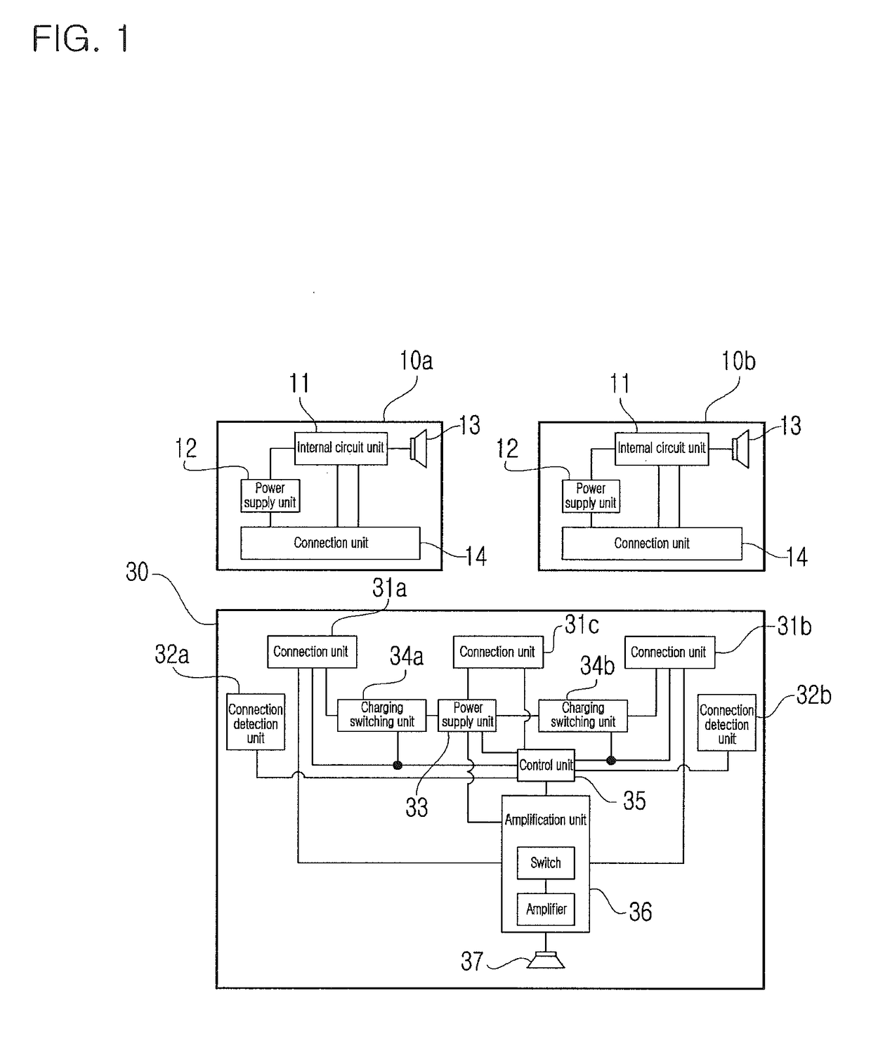
[0055]The wireless earphone system configured as described above operates, as follows:

[0056]When it is necessary to charge the power supply unit 33 of the charging case 30 with power, the power supply unit 33 is charged with DC power by applying the DC power to the power supply unit 33 via the connection unit 31c of the charging case 30. The charging case 30 stores DC power in its own power supply unit 33, and then charges the power supply units 12 of the wireless earphones 10a and 10b using the power of the power supply units 33 and supplies the power as the driving power of the charging case 30 itself, when necessary. Alternatively, the charging case 30 may charge the power supply units 12 of the wireless earphones 10a and 10b with DC power applied via the connection unit 31c and also supply the power as the driving power of the charging case 30 itself by supplying the power directly to the wireless earphones 10a and 10b by means of the power supply units 33.

[0057]When a user con...

second embodiment

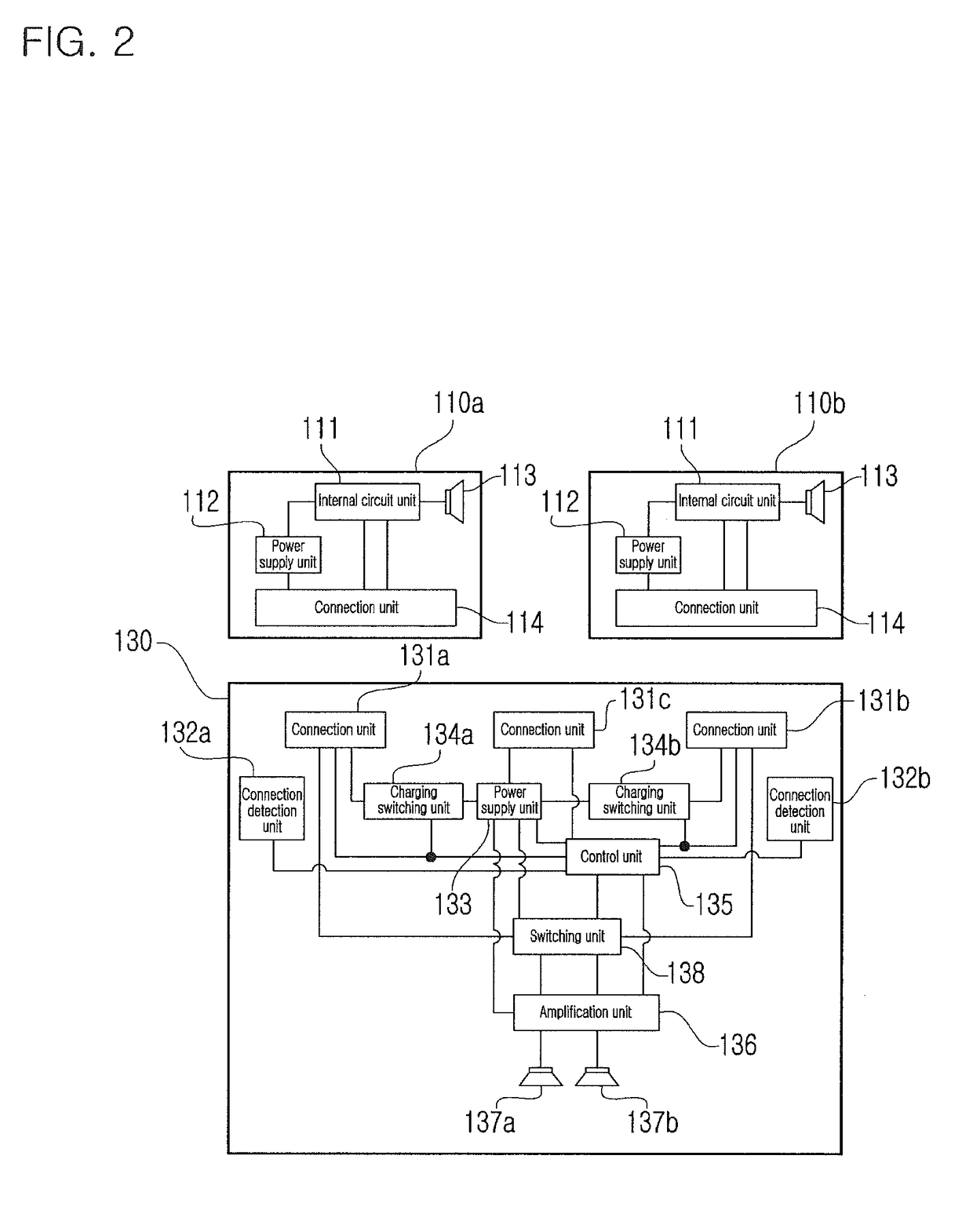
[0069]The wireless earphone system configured as described above operates, as follows:

[0070]When it is necessary to charge the power supply unit 133 of the charging case 130 with power, the power supply unit 133 is charged with DC power by applying the DC power to the power supply unit 133 via the connection unit 131c of the charging case 130. The charging case 130 stores DC power in its own power supply unit 133, and then charges the power supply units 112 of the wireless earphones 110a and 110b using the power of the power supply unit 133 and supplies the power as the driving power of the charging case 130 itself, when necessary. Alternatively, the charging case 130 may charge the power supply units 112 of the wireless earphones 110a and 110b with DC power applied via the connection unit 131c and also supply the power as the driving power of the charging case 130 itself by supplying the power directly to the wireless earphones 110a and 110b by means of the power supply units 133....

third embodiment

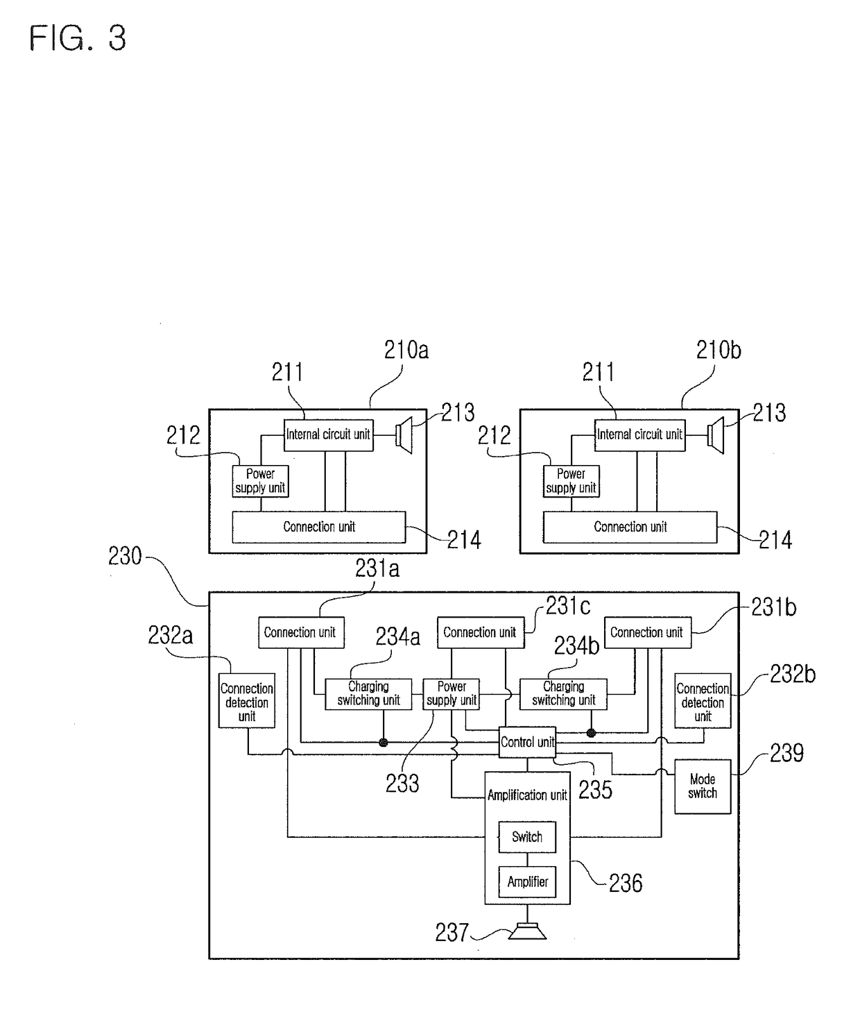
[0082]The wireless earphone system configured as described above operates, as follows:

[0083]When it is necessary to charge the power supply unit 233 of the charging case 230, the power supply unit 233 is charged with power by applying DC power to the power supply unit 233 via the connection unit 231c of the charging case 230. The charging case 230 stores the DC power in its own power supply unit 233, and then charges the power supply units 212 of the wireless earphones 210a and 210b using the power of the power supply unit 233 and also supplies the power as the driving power of the charging case 230 itself, when necessary. Alternatively, the charging case 230 may charge the power supply units 212 of the wireless earphones 210a and 210b with DC power applied via the connection unit 231c and also supply the power as the power driving power of the charging case 230 itself by supplying the power directly to the wireless earphones 210a and 210b by means of the power supply unit 233.

[008...


PUM


Abstract

Disclosed herein is a wireless earphone system. The wireless earphone system includes wireless earphones and a charging case. Each of the wireless earphones includes: a connection unit configured to electrically connect with a charging case; and an internal circuit unit configured to receive a mode switching signal, directing a voice output mode to be switched, applied from the charging case via the connection unit, and to output a sound signal, wirelessly received from an electronic device, to the charging case via the connection unit without outputting the sound signal to a corresponding speaker by itself.

Description

CROSS-REFERENCE TO RELATED APPLICATIONS[0001]This application claims the benefit of Korean Application No. 10-2017-0112000, filed Sep. 1, 2017, and Korean Application No. 10-2018-0090929, filed Aug. 3, 2018, in the Korean Intellectual Property Office. All disclosures of the documents named above are incorporated herein by reference.BACKGROUND1. Technical Field[0002]The present invention relates generally to a wireless earphone system which wirelessly receives sound signals from an electronic device, such as a mobile phone, an audio device, or the like, via short-range wireless communication with the electronic device and outputs the sound signals to a user.2. Description of the Related Art[0003]Generally, wireless earphones are formed in a shape which can be easily carried by a user, and are used in such a way that they are worn in or on the ears of a user. Wireless earphones wirelessly receive sound signals from an electronic device, such as a mobile phone, an audio device, or the ...

Claims


Application Information

Patent Timeline
Patent Type & Authority Applications(United States)
IPC IPC(8): H04R1/10H04R1/02H02J7/00
CPCH04R1/1025H04R1/1016H04R1/1041H04R1/025H02J7/0045H02J7/0052H04R2420/07H04R2201/10H02J7/00
Inventor LEE, JONG BAEOH, SE HONGCHO, EUN YOUNG
Owner CRESYN
Why Eureka
Try Eureka