Improved suspension
a suspension and suspension technology, applied in the field of suspension improvement, can solve problems such as adversely affecting driving comfor
- Summary
- Abstract
- Description
- Claims
- Application Information
AI Technical Summary
Benefits of technology
Problems solved by technology
Method used
Image
Examples
first embodiment
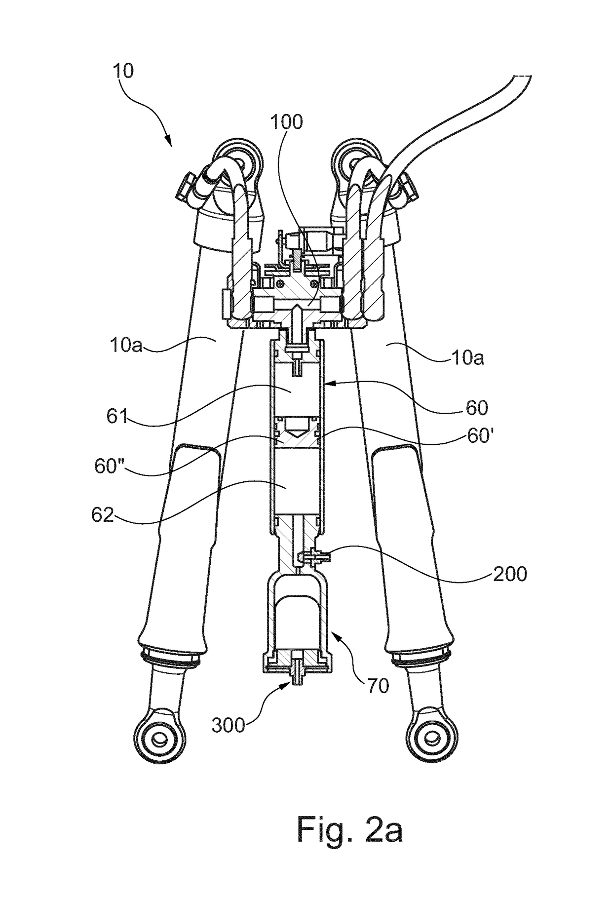
[0045]According to the suspension according to the present invention, and with particular reference to the detail in FIG. 5, the second accumulator 70 having a variable volume comprises a preferably substantially cylindrical containment element 71 defining therein an expansion chamber 72 having a variable volume.
[0046]Separation means are conveniently provided inside said containment element 71 in order to vary the volume of the expansion chamber 72, said separation means 73 being adapted to divide said expansion chamber 72 into two parts; a first part 72′ in fluid communication with said first accumulator 60 and a second part 72″ containing contrast means suitable for counteracting the displacement of said separation means 73, thus counteracting the volume increase of said first part 72′ of said expansion chamber 72.
[0047]According to a first embodiment of the present invention shown in FIGS. 2a to 4, said separation means 73 preferably consist of a balloon 73a.
[0048]Said second p...
second embodiment
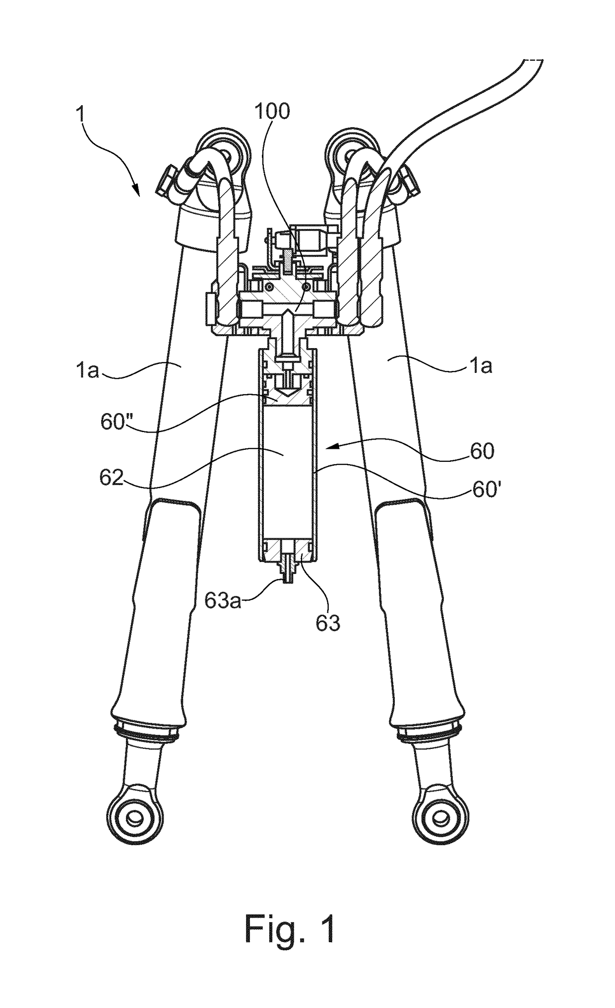
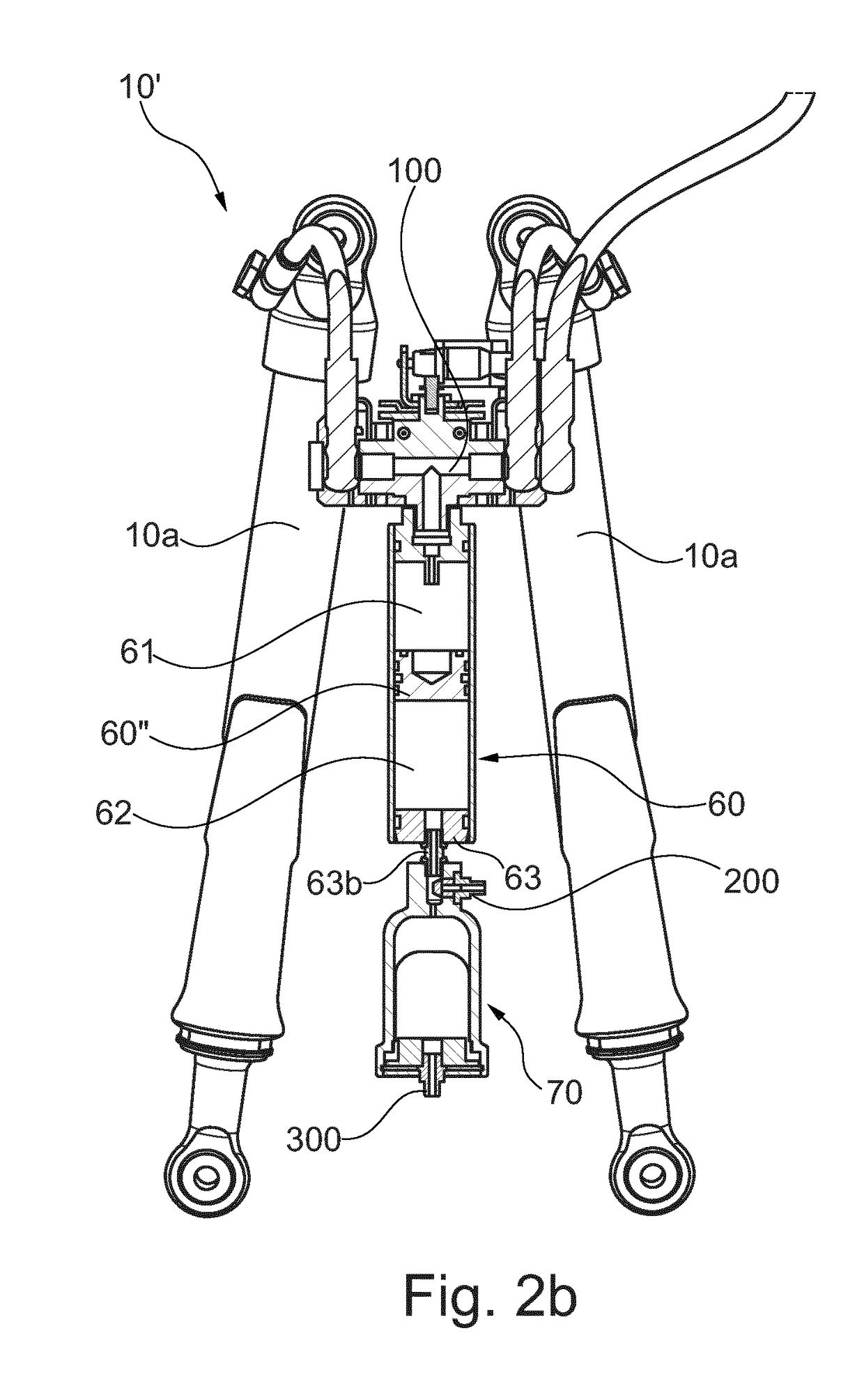
[0050]With reference to FIG. 2b, suspension 10′ according to the present invention differs from the one shown in FIG. 2a in that said second accumulator 70 having a variable volume is directly connected to the closure plug 63 by means of a nipple 63b accommodated in place of valve 63a shown in FIG. 1 in the prepared seat. According to this configuration, the adjustment of the pressure of the lower chamber 62 of said accumulator may be possible only when the second accumulator 70 has been connected, and by means of said first filling valve 200.
[0051]The charge of said second accumulator 70 may occur by means of a dedicated filling valve indicated by numeral 300, which is entirely similar to valve 73b shown in FIG. 5 provided on plug 75 of said second accumulator 70.
[0052]Among the advantages of the configuration shown in FIG. 2b, it is worth noting that the second accumulator 70 having a variable volume can be connected without modifications to the suspension system, and in particula...
third embodiment
[0054]With reference to FIG. 2c, suspension 10″ according to the present invention differs from the one shown in FIG. 2a in that a third accumulator 76 having a variable volume is connected to the second accumulator 70 having a variable volume. The gradual engagement of the suspension may be further improved with this type of configuration, and accordingly the driving comfort, as better explained below.
[0055]Also in this case, the charge of the first accumulator 60 may occur by means of a first filling valve 200, with the second accumulator 70 being connected. Similarly, the charge of the second accumulator 70 may occur by means of a second filling valve 200′ arranged on the stretch of connection connecting said third accumulator 76 with said second accumulator 70. Finally, the charge of said third accumulator 76 occurs by means of a dedicated charge 300 similarly to that described with reference to the embodiments in FIGS. 2a and 2b.
[0056]With reference to FIG. 2d, in this embodim...
PUM
 Abstract
Description
Claims
Application Information
 - R&D
- Intellectual Property
- Life Sciences
- Materials
- Tech Scout
- Unparalleled Data Quality
- Higher Quality Content
- 60% Fewer Hallucinations
Browse by: Latest US Patents, China's latest patents, Technical Efficacy Thesaurus, Application Domain, Technology Topic, Popular Technical Reports.
© 2025 PatSnap. All rights reserved.Legal|Privacy policy|Modern Slavery Act Transparency Statement|Sitemap|About US| Contact US: help@patsnap.com


