Power supply device

a power supply device and power supply technology, applied in the direction of wing accessories, doors, relatively moving parts, etc., can solve the problems of affecting the safety of the door trim, the exterior member abruptly resiliently returning to generate abnormal noise, and the door trim is difficult to catch, so as to reduce the exposure of the wire harness to the door trim, suppress interference, and reduce the effect of the exposure of the wire harness

Active Publication Date: 2019-03-14
YAZAKI CORP
View PDF4 Cites 9 Cited by
  • Summary
  • Abstract
  • Description
  • Claims
  • Application Information

AI Technical Summary

Benefits of technology

[0019]According to the one aspect of the present invention, since when the slide door is in the half opened state, the wire harness is bent downwardly, and at least the part of the wire harness is positioned below the case where the slide door is in the fully opened state or the fully closed state, the wire harness can be bent three-dimensionally. That is, the wire harness can be bent not only in the plane (horizontal plane) including the traveling direction (sliding direction) and the vehicle width direction but also in the space including the vertical direction. By thus bending the wire harness three-dimensionally and moving at least the part of the wire harness downward in the half opened state of the slide door, the wire harness can be easily pulled out from the lower end of the door trim, interference between the wire harness and the door trim can be suppressed. Further, it is only necessary to appropriately bend the wire harness three-dimensionally according to the shape of the door trim or the like to suppress the interference, reducing the exposure of the wire harness in the slide door.
[0020]According to the present invention, the wire harness is swingably supported about the swing axis along the vehicle width direction, so that when the slide door is slid along the traveling direction, the wire harness can be easily bent three-dimensionally. In addition, compared with the configuration in which the main body side end portion is swung, the portion of the wire harness on the side of the slide door easily extends downward in the half opened state, and the wire harness can be easily pulled out from the lower end of the door trim.
[0021]According to the present invention, since the swing support portion for swingably supporting the wire harness is formed separately from the door side support portion for supporting the door side end portion of the wire harness, it is possible to simplify the structure of the swing support portion and to reduce the number of parts, as compared with a configuration in which these are integrated (configuration in which the door side end portion is swingably supported by the door side support portion). That is, even though the electric wire is pulled out from the end portion of the wire harness and the structure of the door side end portion tends to be complicated, the configuration can be simplified because the support at the door side end portion and the support for swing are different.
[0022]According to the present invention, the main body side end portion of the wire harness is rotatably supported about the longitudinal direction, whereby when the wire harness is bent three-dimensionally, the wire harness is hard to be twisted and can be less subjected to damage.
[0023]According to the invention, since the bending restricting member provided in the wire harness has the bending allowance direction and the bending restricting direction in which the bending restricting direction faces the opposite side of the bending allowance direction, the wire harness can be easily bent convexly in a desired direction, but hardly bent convexly on the opposite side. Since the main body side end portion of the wire harness is rotatably supported, the bending restricting member can change direction along with sliding of the slide door, and the direction in which the wire harness is allowed to bend is appropriately changed, so that the wire harness can be easily bent three-dimensionally.
[0024]Further, since the bending restricting direction faces upward in the half opened state of the slide door, the main body side end portion that is supported so as to extend along the horizontal plane can be prevented from being bent convexly upward when the entire wire harness attempts to bend downward convexly, and damage to the wire harness can be suppressed.

Problems solved by technology

However, since the wire harness is bent along with sliding of the slide door, the above-described configuration may change a withdrawal position of the wire harness from the door trim.
As a result, the door trim and the wire harness interfere with each other, resulting in various inconveniences.
For example, an exterior member (corrugated tube or the like) of the wire harness may be caught by the door trim, and when the catch is released, the exterior member abruptly resiliently returns to generate abnormal noises.
In the power supply device described in Patent Document 1, since the protruding portion is provided in the corrugated tube and the protruding portion is formed to have a larger diameter than the other portions, the door trim is difficult to be caught, suppressing abnormal noises from occurring.

Method used


Image

  • Power supply device
  • Power supply device
  • Power supply device

Examples


first embodiment

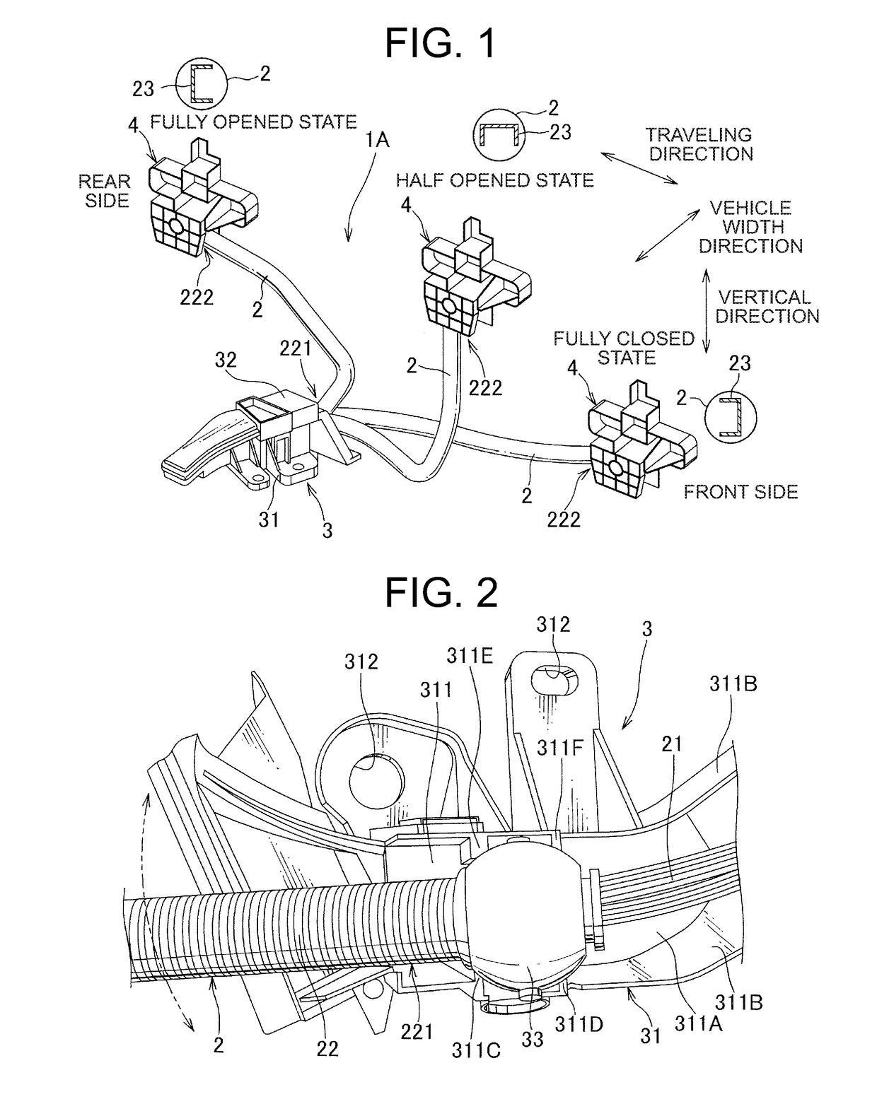
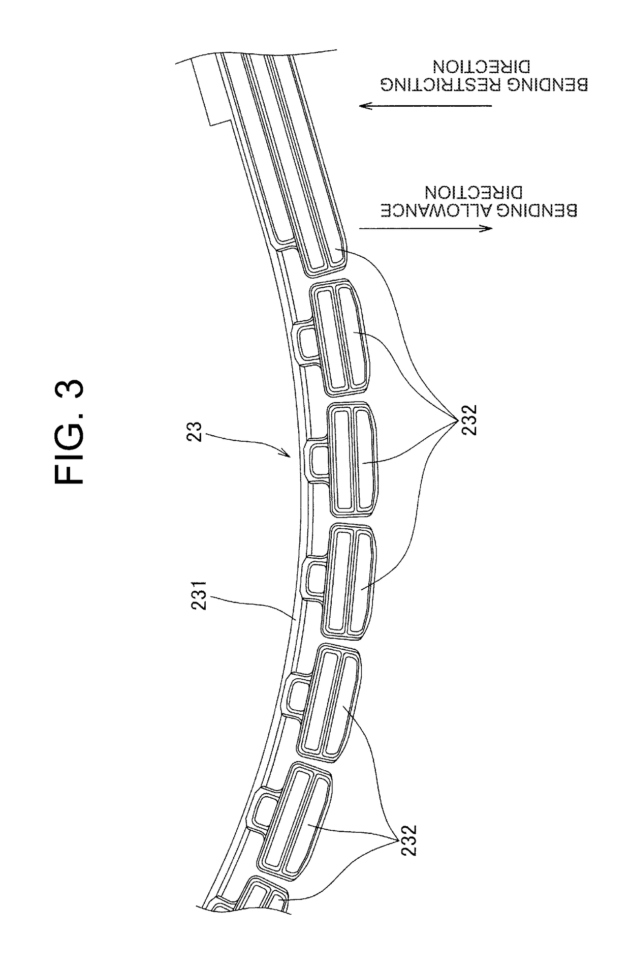
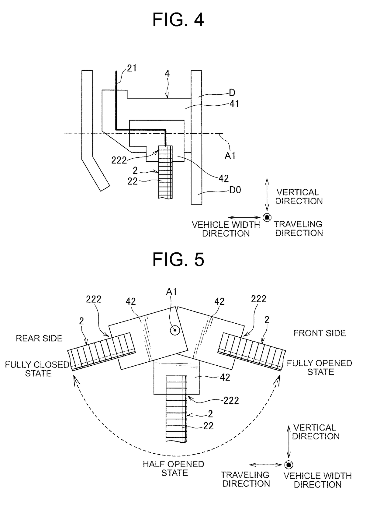
[0062]Hereinafter, a first embodiment of the present invention will be described with reference to the drawings. FIG. 1 is a perspective view showing a power supply device 1A according to a first embodiment of the present invention, FIG. 2 is a perspective view showing a main part of a main body side unit 3 of the power supply device 1A, FIG. 3 is a perspective view showing a bending restricting member 23 provided in a wire harness 2 of the power supply device 1A, FIG. 4 is a front view showing the door side unit 4 of the power supply device 1A, FIG. 5 shows a main portion of the door side unit 4, and FIGS. 6(A) to 6(C) are perspective views showing how the wire harness 2 is bent when the slide door slides in a vehicle provided with the power supply device 1A.

[0063]The power supply device 1A according to the present embodiment is provided in a vehicle having a slide door that slides along a traveling direction and is for supplying power from the vehicle body to the slide door, and i...

second embodiment

[0095]Hereinafter, a second embodiment of the present invention will be described with reference to the drawings. FIGS. 10(A) to 10(C) are perspective views showing how the wire harness 5 bends when the slide door slides in the vehicle provided with the power supply device according to the second embodiment of the present invention.

[0096]The power supply device of the present embodiment is provided with a wire harness 5 shown in FIGS. 10(A) to 10(C) in place of the wire harness 2 of the power supply device 1A of the first embodiment. The wire harness 5 has a plurality of electric wires (not shown) and a chain member 51 as an exterior member provided to cover the outer periphery of the electric wire.

[0097]A ball portion similar to the ball portion 33 of the first embodiment is fixed to the main body side end portion 511 of the chain member 51 and the main body side end portion 511 is rotatably supported about a rotation axis along the longitudinal direction of the wire harness 5 by t...


PUM


Abstract

Provided is an electric power supply device in which exposure of a wire harness can be reduced in a slide door and interference with door trim can be minimized. When a slide door is half opened, a wire harness bends convexly downward, and one portion thereof is positioned lower than when the slide door is fully open or fully closed. Specifically, the wire harness is bent three-dimensionally. This makes it easier for the wire harness to be pulled out from a bottom end of door trim, and makes it possible for interference between the wire harness and the door trim to be minimized. The wire harness may be also bent three-dimensionally as appropriate in accordance with a shape of the door trim, reducing exposure of the wire harness in the slide door.

Description

TECHNICAL FIELD[0001]The present invention relates to a power supply device for supplying power from a vehicle body to a slide door in a vehicle having a slide door.BACKGROUND ART[0002]Generally, a vehicle equipped with a slide door is provided with a power supply device for supplying power from a vehicle body to the slide door. That is, the wire harness of the power supply device electrically connects a battery etc. mounted on the vehicle body and an electrical component provided on the slide door so that electric power is supplied. In such a power supply device, it is preferable to make the wire harness less exposed in the slide door, and thus such configuration was sometimes adapted that the wire harness is hidden by the door trim and is drawn out from a lower end or front and rear ends of the door trim toward the vehicle body.[0003]However, since the wire harness is bent along with sliding of the slide door, the above-described configuration may change a withdrawal position of t...

Claims


Application Information

Patent Timeline
Patent Type & Authority Applications(United States)
IPC IPC(8): B60R16/02B60R16/03B60J5/06H02G3/04
CPCB60R16/0215B60R16/03B60J5/06H02G3/0462E05F15/689E05Y2400/654E05Y2900/55B60R16/02H02G3/04H02G11/00B60R16/027H02G3/0468H02G11/006B60R16/0207
Inventor KOGURE, NAOTOTOMOSADA, KOSUKESEKINO, TSUKASA
Owner YAZAKI CORP
Why Eureka
Try Eureka