Duty cycle correction circuit and clock correction circuit including the same

a technology of duty cycle correction and clock correction, which is applied in the direction of pulse manipulation, pulse technique, electrical equipment, etc., can solve the problem of becoming burdensom

Inactive Publication Date: 2019-03-14
SK HYNIX INC +1
View PDF5 Cites 20 Cited by
  • Summary
  • Abstract
  • Description
  • Claims
  • Application Information

AI Technical Summary

Problems solved by technology

As the data transfer rate of diverse integrated circuits, such as a memory, increases, it becomes burdensome to use a clock of a high frequency for transferring data between integrated circuits in the inside of an integrated circuit, for example, a semiconductor memory device.
However, when the multi-phase clocks ICK, QCK, IBCK and QBCK are used in the inside of an actual integrated circuit, for example, a semiconductor memory device, the phase difference between the clocks ICK, QCK, IBCK and QBCK is not maintained at approximately 90 θ due to various noises in the inside of the integrated circuit, and the duty cycle ratio of the clocks ICK, QCK, IBCK and QBCK is not maintained at approximately 50%.

Method used


Image

  • Duty cycle correction circuit and clock correction circuit including the same
  • Duty cycle correction circuit and clock correction circuit including the same
  • Duty cycle correction circuit and clock correction circuit including the same

Examples


Embodiment Construction

[0042]Exemplary embodiments of the present invention will be described below in more detail with reference to the accompanying drawings. The present invention may, however, be embodied in different forms and should not be construed as limited to the embodiments set forth herein. Rather, these embodiments are provided so that this disclosure will be thorough and complete, and will fully convey the scope of the present invention to those skilled in the art. Throughout the disclosure, like reference numerals refer to like parts throughout the various figures and embodiments of the present invention.

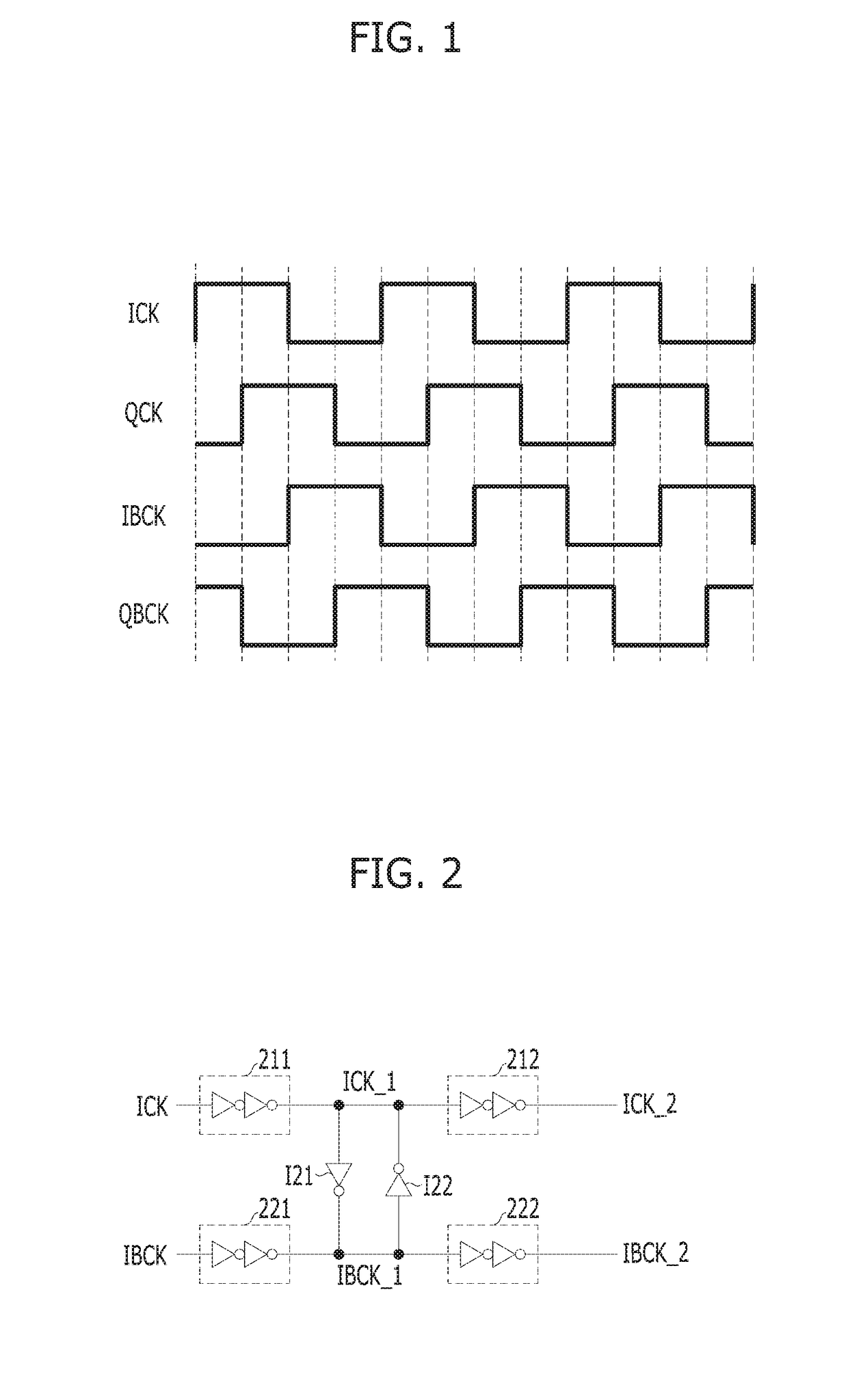
[0043]FIG. 2 is a schematic diagram illustrating inverters that are coupled in a cross-coupled form that is used to prevent an enable section of a clock ICK and an enable section of a clock IBCK from overlapping with each other in accordance with an embodiment of the present invention.

[0044]Referring to FIG. 2, drivers 211 and 212 may be used to transfer the clock ICK in the inside of an int...


PUM


Abstract

A duty cycle correction circuit includes a first inverter suitable for driving a second clock in response to a first clock; a second inverter suitable for driving the first clock in response to the second clock; and a duty cycle detector suitable for detecting a duty cycle of the first clock or the second clock, wherein driving forces of one or more inverters among the first inverter and the second inverter are controlled based on a duty detection result of the duty cycle detector.

Description

CROSS-REFERENCE TO RELATED APPLICATIONS[0001]The present application claims priority of Korean Patent Application No. 10-2017-0116486, filed on Sep. 12, 2017, which is incorporated herein by reference in its entirety.BACKGROUND1. Field[0002]Exemplary embodiments of the present invention relate to a duty cycle correction circuit and a clock correction circuit including the duty cycle correction circuit.2. Description of the Related Art[0003]As the data transfer rate of diverse integrated circuits, such as a memory, increases, it becomes burdensome to use a clock of a high frequency for transferring data between integrated circuits in the inside of an integrated circuit, for example, a semiconductor memory device. To solve this problem, multi-phase clocks of lower frequencies than the clock used for transferring data between integrated circuits may be used in the inside of an integrated circuit chip, for example a semiconductor memory device.[0004]FIG. 1 illustrates an example of mult...

Claims


Application Information

Patent Timeline
Patent Type & Authority Applications(United States)
IPC IPC(8): H03K5/156
CPCH03K5/1565H03K5/14H03K5/156
Inventor KIM, SUHWANCHAE, JOO-HYUNGJEONG, DEOG-KYOON
Owner SK HYNIX INC
Why Eureka
Try Eureka