Ring oscillator and multi-phase clock correction circuit using the same

a multi-phase clock and oscillator technology, applied in pulse manipulation, pulse technique, instruments, etc., can solve the problems of not being suitable for current design semiconductor devices, and achieve the effects of low jitter characteristics, low power consumption, and high speed operation

Inactive Publication Date: 2009-12-31
SK HYNIX INC
View PDF7 Cites 20 Cited by
  • Summary
  • Abstract
  • Description
  • Claims
  • Application Information

AI Technical Summary

Benefits of technology

[0012]The ring oscillator in accordance with the invention employs a plurality of buffers having a cross-coupled structure, which is capable of generating clock signals of a CML level, thereby generating clock signals that consume less power in a high speed operation and have low jitter characteristics. In addition, the ring oscillator in accordanc...

Problems solved by technology

However, the existing ring oscillator by its configuration has to generate a CMOS level clock signal ra...

Method used


Image

  • Ring oscillator and multi-phase clock correction circuit using the same
  • Ring oscillator and multi-phase clock correction circuit using the same
  • Ring oscillator and multi-phase clock correction circuit using the same

Examples


Embodiment Construction

[0017]Hereinafter, a preferred embodiment in accordance with the present invention will be described in detail with reference to the accompanying drawings so that the invention can readily be practiced by those skilled in the art to which the invention pertains.

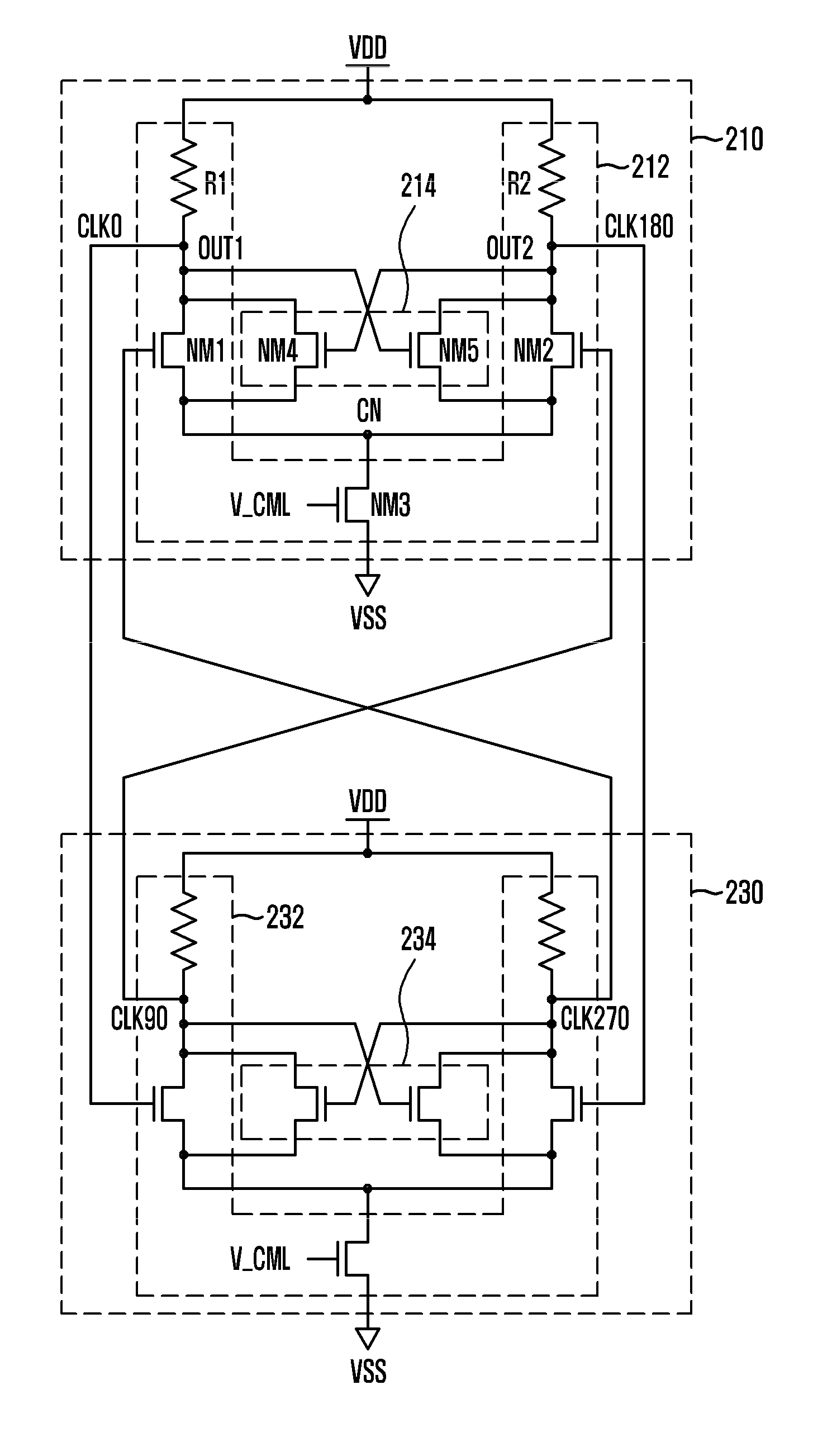
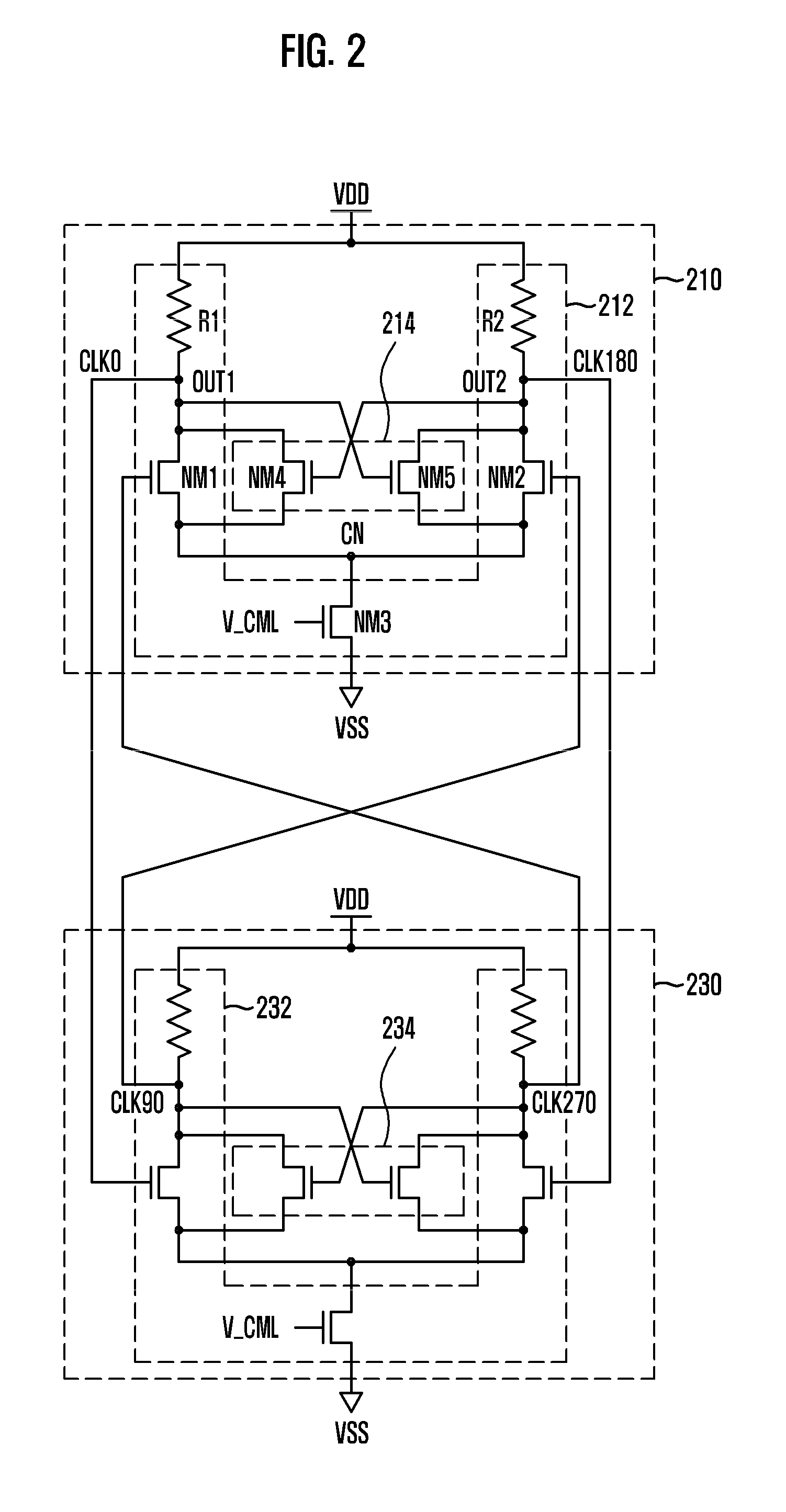
[0018]FIG. 2 is a circuit diagram for explaining a ring oscillator in accordance with an embodiment of the invention.

[0019]Referring to FIG. 2, the ring oscillator of the invention is for generating first to fourth clock signals CLK0, CLK90, CLK180, and CLK270 of a CML level having predetermined phase differences, and can include first and second buffer units 210 and 230. The first and second buffer units 210 and 230 have a cross-coupled structure, and generate first to fourth clock signals CLK0, CLK90, CLK180, and CLK270 using a bias voltage V_CML having a predetermined voltage level applied thereto.

[0020]Here, the first buffer unit 210 is for buffering the second and the fourth clock signals CLK90 and CLK270 which are outpu...


PUM


Abstract

A ring oscillator including a plurality of buffer units, each of which has a cross-coupled structure, for generating clock signals using a bias voltage having a predetermined voltage level applied thereto, wherein the clock signals have a swing width corresponding to the bias voltage.

Description

CROSS-REFERENCE TO RELATED APPLICATION[0001]The present invention claims priority from Korean patent application number 10-2008-0063134, filed on Jun. 30, 2008, which is incorporated by reference in its entirety.BACKGROUND OF THE INVENTION[0002]The present invention relates to a semiconductor design technology, and more particularly, to a ring oscillator for generating an oscillating clock signal and a multi-phase clock correction circuit for correcting the phase of a multi-phase clock signal using the same. In general, a semiconductor device, such as Double Data Rate Synchronous DRAM (DDR SDRAM), includes diverse circuits for performing a variety of circuit operations. As one of these diverse circuits, there is a ring oscillator. Typically, the ring oscillator is provided with an odd number of inverters to generate an oscillating clock signal. Recently, however, a ring oscillator with an even number of inverters as shown in FIG. 1 has been mainly employed.[0003]Referring to the cir...

Claims


Application Information

Patent Timeline
IPC IPC(8): H03K5/12H03K3/03
CPCH03K23/542H03K3/0322G11C7/222G11C11/4076G11C2207/2254
Inventor SONG, TAEK-SANGKWON, DAE-HANYOON, DAE-KUN
Owner SK HYNIX INC
Why Eureka
Try Eureka