Sole Structure for a Sports Shoe

a technology for sports shoes and soles, applied in the field of sports shoe sole structures, can solve the problems of energy loss, energy loss, and excessive bending of local shoes, and achieve the effect of improving the cushioning properties

Inactive Publication Date: 2019-03-21
MIZUNO CORPORATION
View PDF7 Cites 28 Cited by
  • Summary
  • Abstract
  • Description
  • Claims
  • Application Information

AI Technical Summary

Benefits of technology

[0012]When the forefoot region of the sole structure is going to bend along the sole bent groove of the outsole at the time of bending of the sole structure, the thick part of the upper midsole or the lower midsole of a relatively greater hardness disposed at the sole bent groove is also going to bend at the same time. However, since such a thick part is a high-rigidity part, it has a greater bending resistance and it thus prevents an excessive bending locally along the sole bent groove of the sole structure. Thereby, bendability of the forefoot region can be controlled and an occurrence of an energy loss resulted from a locally excessive bending can be prevented.
[0015]When the forefoot region of the sole structure is going to bend along the sole bent groove of the outsole at the time of bending of the sole structure, the thick part of the upper midsole or the lower midsole disposed at the position on of the sole bent groove is also going to bend at the same time. However, since such a thick part is a high-rigidity part, it has a greater bending resistance and it thus prevents an excessive bending locally along the sole bent groove of the sole structure. Thereby, bendability of the forefoot region can be controlled and an occurrence of an energy loss resulted from the locally excessive bending can be prevented.
[0025]The upper surface of the lower midsole or the lower surface of the upper midsole without the corrugated surfaces may have a planar surface, and there may be formed a gap between the planar surface and the lower surface of the upper midsole or the upper surface of the lower midsole. Thus, when a load is transferred to the forefoot region of the sole structure, cushioning properties is improved.

Problems solved by technology

However, in the structure of EP3146862A2, at the time of bending of the midsole, an excessive bending is likely to occur locally at the troughs of the zigzag-shaped midsole.
An occurrence of such a locally excessive bending causes an energy loss.
In the structure of JP Pat. No. 3403952, since the soft upper midsole is exposed at the bottom portion of the sole bent groove, an excessive bending is similarly likely to occur to cause an energy loss at the time of bending along the sole bent groove.

Method used


Image

  • Sole Structure for a Sports Shoe
  • Sole Structure for a Sports Shoe
  • Sole Structure for a Sports Shoe

Examples


first alternative embodiment

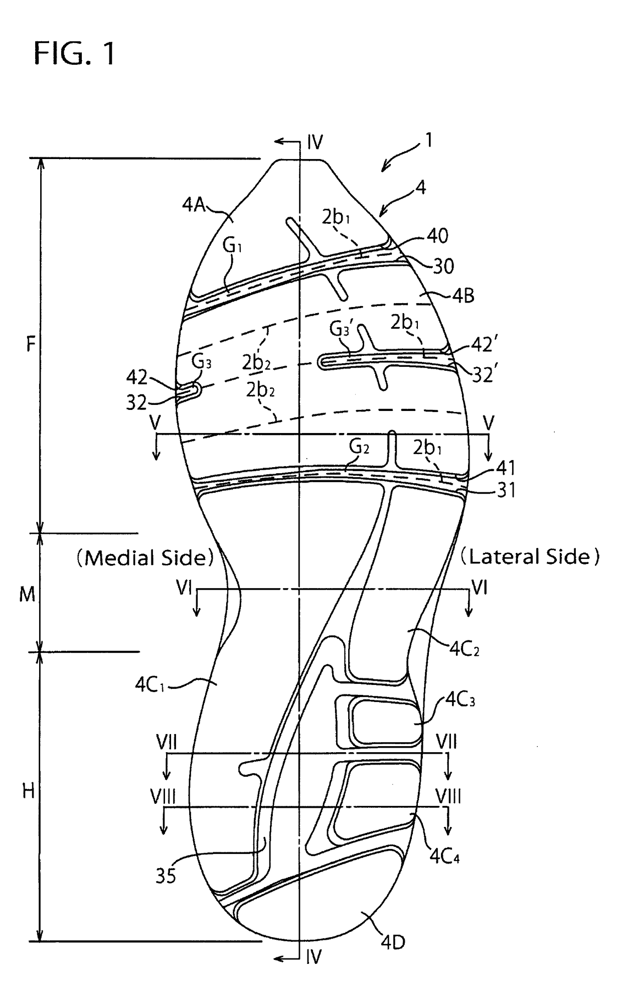
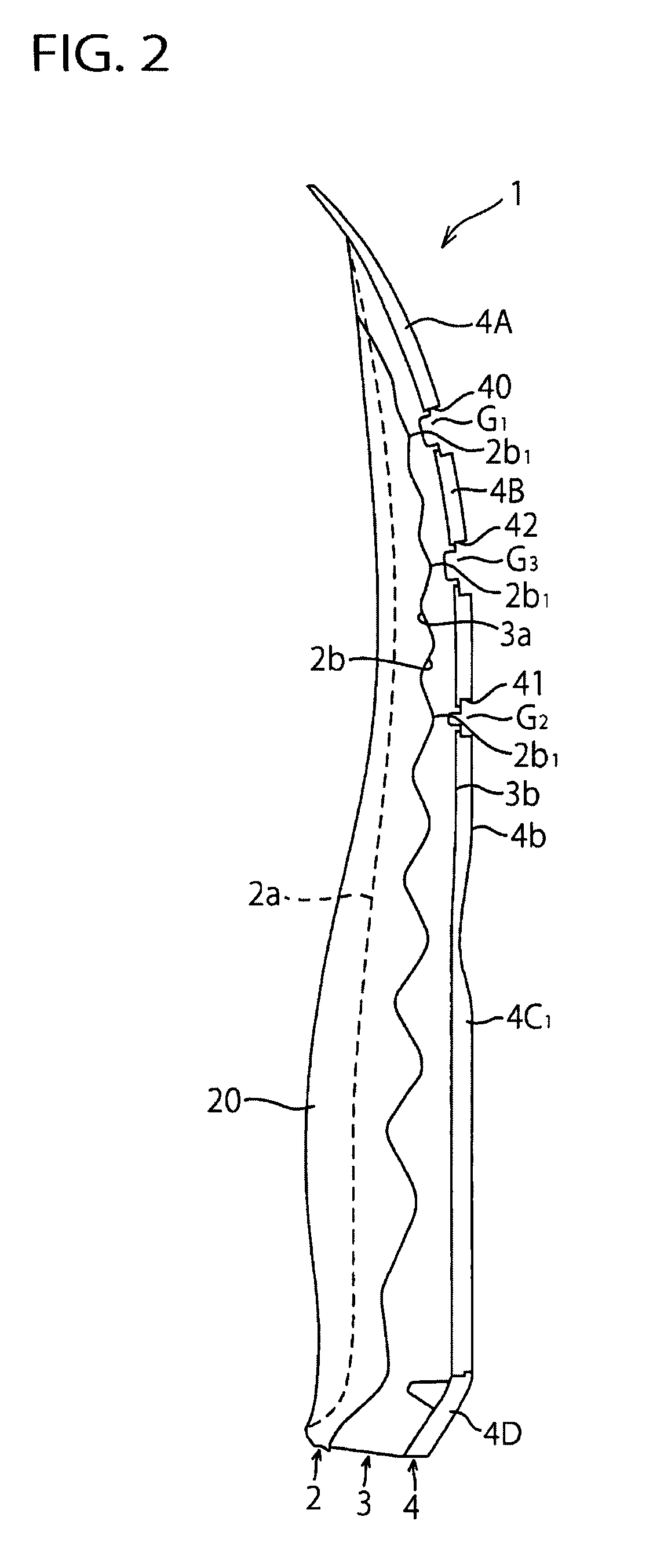
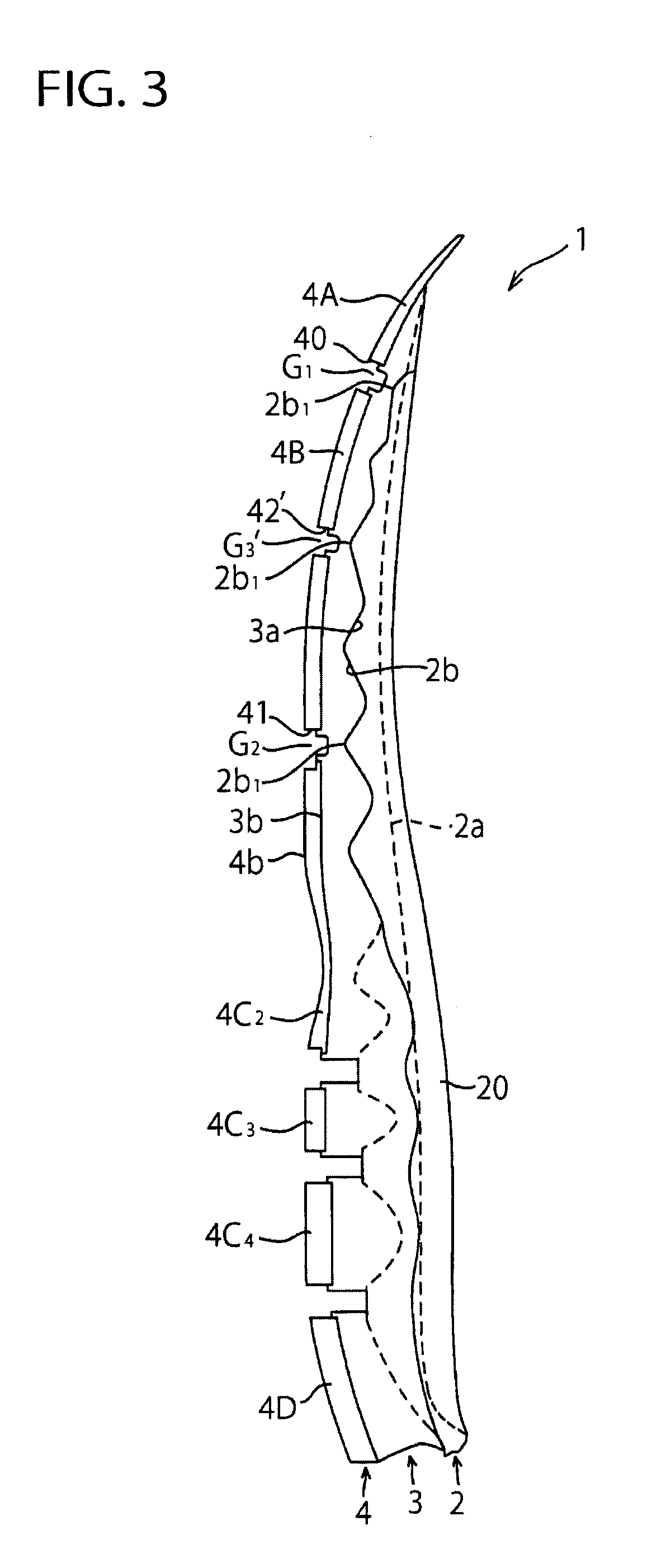
[0079]In the above-mentioned embodiment, an example was shown in which the sole bent grooves G1, G2, G3, G3′ provided at the forefoot region F of the sole structure 1 comprise the slits (or through grooves) 40, 41, 42, 42′ passing through the outsole 4 and the concave grooves (or blind grooves) 30, 31, 32, 32′ formed on the lower midsole 3, respectively but application of the present invention is not limited to such an example.

[0080]FIGS. 14 to 21 show a sole structure of a sports shoe according to a first alternative embodiment. In these drawings, like reference numbers indicate identical or functionally similar elements. Here, an indoor sports shoe is taken for an example of the sports shoe. As shown in FIGS. 14 to 21, in this first alternative embodiment, there are provided sole bent grooves G1, G2, G3 at the forefoot region F of the sole structure 1, which are formed of concave grooves (or blind grooves) 45, 46, 47 respectively formed on the ground contact surface of the outsole...

second alternative embodiment

[0086]In the above-mentioned embodiment and the first alternative embodiment, an example was shown in which the ridge lines 2b1 of the wavy shapes of the lower surface 2b of the upper midsole 2 extend across the entire width of the sole (that is, from the medial side end to the lateral side end), but application of the present invention is not limited to such an example.

[0087]FIGS. 22 to 25 show a sole structure of a sports shoe according to a second alternative embodiment. Here, a running shoe is taken for an example of the sports shoe. In these drawings, like reference numbers indicate identical or functionally similar elements.

[0088]As shown in FIGS. 22 to 25, in this second alternative embodiment, at the longitudinally and laterally central part of the upper midsole 2 in the forefoot region F of the sole structure 1, there is formed a concavity 28 that opens to the side of the lower surface 2b. In this example, the concavity 28 is a generally rectangular shaped blind hole that i...

third alternative embodiment

[0107]FIG. 26 shows a third alternative embodiment of the present invention and it corresponds to FIG. 2 of the above-mentioned embodiment. In FIG. 26, like reference numbers indicates identical or functionally similar elements to those in FIG. 2. In the above-mentioned embodiment, an example was shown in which the hardness of the upper midsole 2 is higher than the hardness of the lower midsole 3, but in this third alternative embodiment, contrary to such an example, the hardness of the lower midsole 3 is higher than the hardness of the upper midsole 2.

[0108]Specifically, the hardness of the lower midsole 3 is set to, for example 60±4 C in the Asker C scale and the hardness of the upper midsole 2 is set to, for example 50±4 C in the Asker C scale. A difference between the hardness of the upper midsole 2 and the hardness of the lower midsole 3 is preferably approximately 5 C.

[0109]Also, in this third alternative embodiment, a phase of the wavy shapes of the upper and lower midsoles 2...


PUM

PropertyMeasurementUnit
widthaaaaaaaaaa
hardnessaaaaaaaaaa
thicknessaaaaaaaaaa

Abstract

A sole structure for a sports shoe that controls bendability of a forefoot region of the sole structure. The sole structure includes an upper midsole disposed on an upper side of the forefoot region of the sports shoe and formed of a soft elastic material, a lower midsole disposed under the upper midsole and formed of a soft elastic material, and an outsole that is disposed on a lower surface of the lower midsole and that has sole bent grooves extending substantially in a sole width direction. Both the lower surface of the upper midsole and the upper surface of the lower midsole have corrugated mating surfaces that are formed of wavy shapes extending substantially in a sole longitudinal direction. Ridge lines and trough lines of the wavy shapes of the upper midsole extend substantially in the sole width direction. The ridge lines of the wavy shapes of the upper midsole of a relatively higher hardness are overlapped with the sole bent grooves of the outsole in a vertical direction.

Description

BACKGROUND OF THE INVENTION[0001]The present invention relates generally to a sole structure for a sports shoe, and more particularly, to the sole structure that can control bendability of a forefoot region by preventing an excessive bending of the forefoot region.[0002]EP3146862A2 discloses an article of footwear that includes a midsole having an undulating (i.e. zigzag) shape with alternating peaks and troughs in a sole longitudinal direction (see para. [0018] and FIGS. 1 and 2). The midsole has a gap formed between the adjacent peaks (i.e. above the trough between the adjacent peaks) and between the adjacent troughs (i.e. below the peak between the adjacent troughs). The gap between the adjacent peaks and the gap between the adjacent troughs extend across the entire width of the midsole (see para. [0018] and FIGS. 1 and 2).[0003]In the sole structure described in EP3146862A2, when the troughs of the undulating (or zigzag-shaped) midsole contact the ground surface a compressive fo...

Claims


Application Information

Patent Timeline
Patent Type & Authority Applications(United States)
IPC IPC(8): A43B13/12A43B13/14A43B13/04A43B5/06A43B13/22A43B13/16
CPCA43B13/127A43B13/14A43B13/04A43B5/06A43B13/22A43B13/16A43B13/146A43B13/026A43B13/141A43B13/185
Inventor IUCHI, KAZUNORIODA, TAKAOHIRAI, SHINUDA, MASASHIYAMADA, AYAKA
Owner MIZUNO CORPORATION
Why Eureka
Try Eureka