Vehicle surroundings monitoring apparatus

a technology for monitoring apparatus and vehicle surroundings, which is applied in the direction of measuring devices, using reradiation, instruments, etc., can solve the problems of increasing the possibility that the time required for detecting objects also becomes relatively long, affecting the accuracy of detecting objects, so as to reduce the possibility of occurrence of interference and prevent the effect of interferen

Active Publication Date: 2019-03-21
TOYOTA JIDOSHA KK +1
View PDF3 Cites 8 Cited by
  • Summary
  • Abstract
  • Description
  • Claims
  • Application Information

AI Technical Summary

Benefits of technology

[0008]In view of the foregoing, the present invention is made in order to solve the problems described above. That is, one of objects of the present invention is, in a vehicle surroundings monitoring apparatus having at least four radars, each disposed at each of the four corners of a vehicle body, in order to detect an object present around the own vehicle, to prevent the occurrence of the interference of the radio waves transmitted by the radars while reducing the possibility of occurrence of the delay in monitoring (detecting) the object.
[0014]Therefore, the interference of / between the radio waves associated with the two radars adjacent to each other in the lateral direction (for example, the forward right radar and the forward left radar) or in the longitudinal direction (for example, the forward right radar and the backward right radar) is avoided, whereby the deterioration (degradation) of the accuracy for detecting an object by the radars is prevented. In addition, the four radars are divided into two groups (namely, the first diagonal radars and the second diagonal radars), and the transmission periods which are mutually exclusive to each other are assigned for each of the two groups. Namely, the first transmission period and the second transmission period do not overlap with each other. Therefore, the time duration for completing the transmission of the radio waves by all of the four radars becomes shorter compared with the case where the transmission periods which are mutually exclusive to each other are assigned for each of the four radars. Consequently, the case that the time duration for detecting an object around the own vehicle by the four radars (detecting duration) becomes excessively long is avoided.
[0015]For example, a drive support system which assists drive operation of the driver of the own vehicle on the basis of information about an object around the own vehicle detected by the vehicle surroundings monitoring apparatus according to the present invention can quickly obtain the information about the object with high detection accuracy. Therefore, such a drive support system can perform the drive assist control appropriately.
[0022]Therefore, the first diagonal radars continue transmitting the radio waves during the period when the second diagonal radars do not transmit the radio waves, and the second diagonal radars continue transmitting the radio waves during the period when the first diagonal radars do not transmit the radio waves. Consequently, the detecting duration does not become excessively long.
[0038]According to the present aspect, in the manner described above, it is possible to have the four radars cooperate with each other by use of the first synchronization signal and the second synchronization signal so as to control the transmission timings of the radio waves from the four radars by simple processes.

Problems solved by technology

In the overlapping areas X where two detection areas A overlap with each other, the radio waves transmitted by the radars interfere with each other, and thus, the accuracy for detecting an object may degrade.
However, in this case, the time duration for completing the transmission of the radio waves from all of the four radars becomes relatively long, thereby increasing the possibility that the time required for detecting an object also becomes relatively long.
As a result, a considerable delay may occur in performing drive assist controls such as in predicting a probability of a collision.
Thus, the interference between / of the radio waves likely to occur in the overlapping areas.

Method used


Image

  • Vehicle surroundings monitoring apparatus
  • Vehicle surroundings monitoring apparatus
  • Vehicle surroundings monitoring apparatus

Examples


Embodiment Construction

[0050]A vehicle surroundings monitoring apparatus according to an embodiment of the present invention will be described with reference to the drawings.

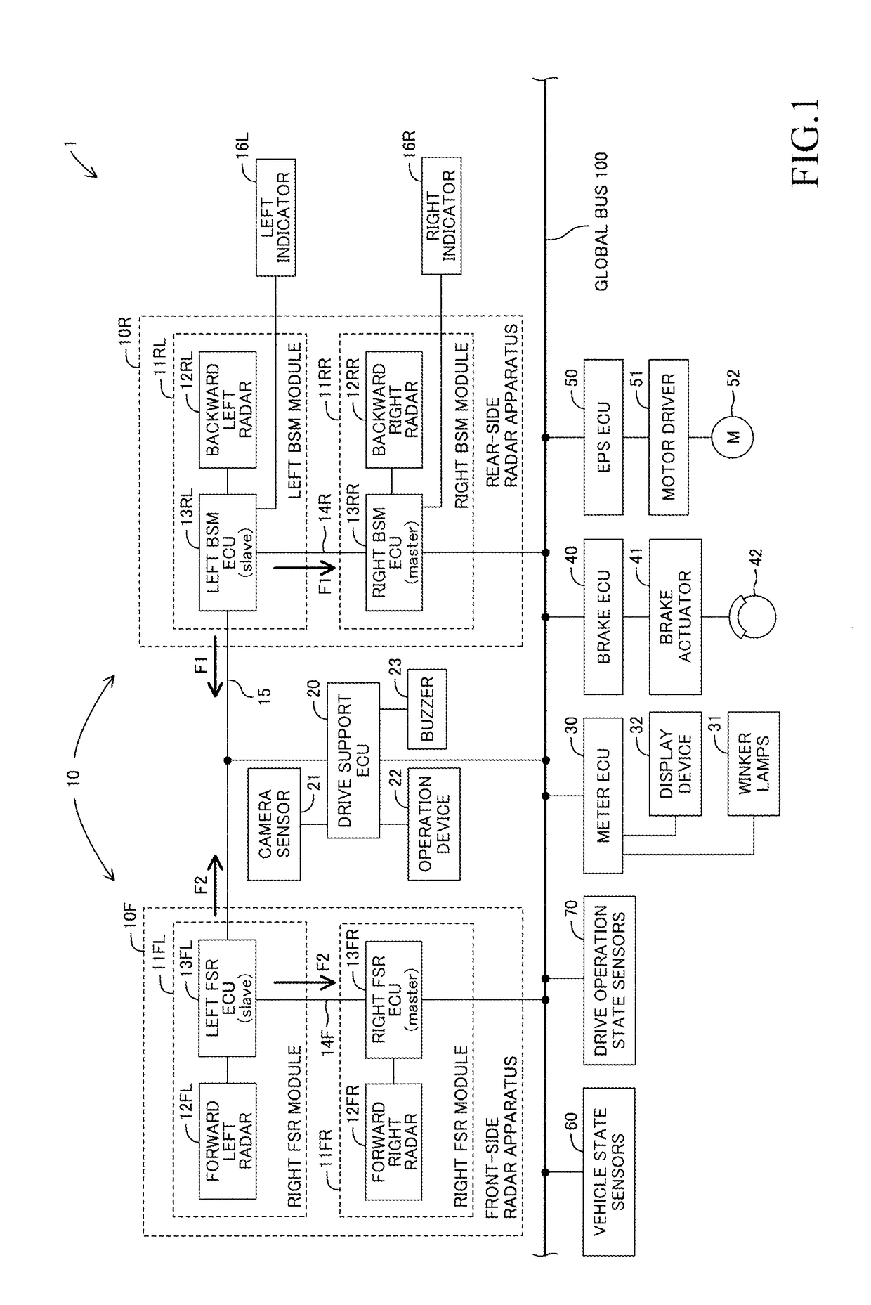
[0051]FIG. 1 shows a schematic diagram of a drive support system 1 equipped with a vehicle surroundings monitoring apparatus 10 according to the present embodiment of the present invention. The drive support system 1 is installed (mounted) on a vehicle (hereinafter also referred to as an “own vehicle” in order to distinguish the own vehicle from other vehicles).

[0052]The drive support system 1 is equipped with a drive support ECU 20, a meter ECU 30, a brake ECU 40, and an electric power steering ECU 50 as well as the vehicle surroundings monitoring apparatus 10.

[0053]Each of the ECUs is an Electric Control Unit which is equipped with a microcomputer as a main component. These ECUs are connected to each other via a global bus 100 which is a communication line (data bus) of a Controller Area Network (CAN) so as to send information to th...


PUM


Abstract

If a vehicle surroundings monitoring apparatus is equipped with four radars disposed at each of the four corners of the body of a vehicle in order to detect an object around the vehicle, the interfere of the radio waves of the radars likely to occur. As a result, the accuracy for detecting an object by the radars will deteriorate. Specifically, if two of detection areas are adjacent to each other of the radars overlaps with each other and the two of the radars transmits radio waves at the same time, the interfere of the radio waves will occur in the overlapping area. In view of this, the four radars are divided into two groups such that the detection areas of two radars within the group aren't adjacent to each other and transmission period of one of the groups and that of the other of the groups are repeated alternately.

Description

BACKGROUNDTechnical Field[0001]The present disclosure relates to a vehicle surroundings monitoring apparatus which detects an object around a vehicle (own vehicle) by use of radars.Description of the Related Art[0002]A vehicle surroundings monitoring apparatus which detects an object around an own vehicle by use of a plurality of radars is known (see, for example, Japanese Patent Application Laid-Open (kokai) No. H07-248382). Each of the radars transmits a radio wave and receives a reflected wave generated by an object reflecting the transmitted wave, to thereby detect a relative position, a relative speed, and the like of the object with respect to the own vehicle. The vehicle surroundings monitoring apparatus is installed on a drive support system which performs drive assist controls so as to assist drive operation of a driver and provides information (the relative position, the relative speed, and the like) about an object detected by the radars to the drive support system. The d...

Claims


Application Information

Patent Timeline
Patent Type & Authority Applications(United States)
IPC IPC(8): G01S7/02G01S13/04G01S13/93G01S13/931
CPCG01S7/023G01S13/04G01S13/931G01S2013/9332G01S2013/9375G01S2013/9378B60W30/08B60W50/08G01S13/87G01S2013/9315G01S2013/93272G01S2013/93271G01S7/0235
Inventor TAKEUCHI, KOJIKAMINADE, TAKUYAHONMA, YOJI
Owner TOYOTA JIDOSHA KK
Why Eureka
Try Eureka