
Goa drive unit and goa drive circuit

Active Publication Date: 2019-03-21
WUHAN CHINA STAR OPTOELECTRONICS TECH CO LTD
View PDF2 Cites 3 Cited by
  • Summary
  • Abstract
  • Description
  • Claims
  • Application Information

AI Technical Summary

Benefits of technology

The present invention aims to improve the reliability of a gate driver circuit for TFT devices by reducing the risk of efficacy loss. This is achieved by using complementary control signals that control the opening and closing of the TFT devices, resulting in a shortened duration of constant active use for each device and lower stress levels. This reduces the risk of TFT device failure and improves the overall reliability of the gate driver circuit.

Problems solved by technology

Under the influence of such stress, the electronic mobility of the TFT devices will change, so as to deviate a threshold voltage of the TFT devices, leading to the efficacy loss of the TFT devices.
For example, with respect to the bidirectional selection unit in the GOA drive circuit, the TFT devices, which constitute the bidirectional selection unit, are always required to keep in the active state in the line scanning procedure, and thus in a high risk of efficacy loss.
This will severely influence the reliability of the GOA drive circuit.

Method used


Image

  • Goa drive unit and goa drive circuit
  • Goa drive unit and goa drive circuit

Examples


embodiment 1

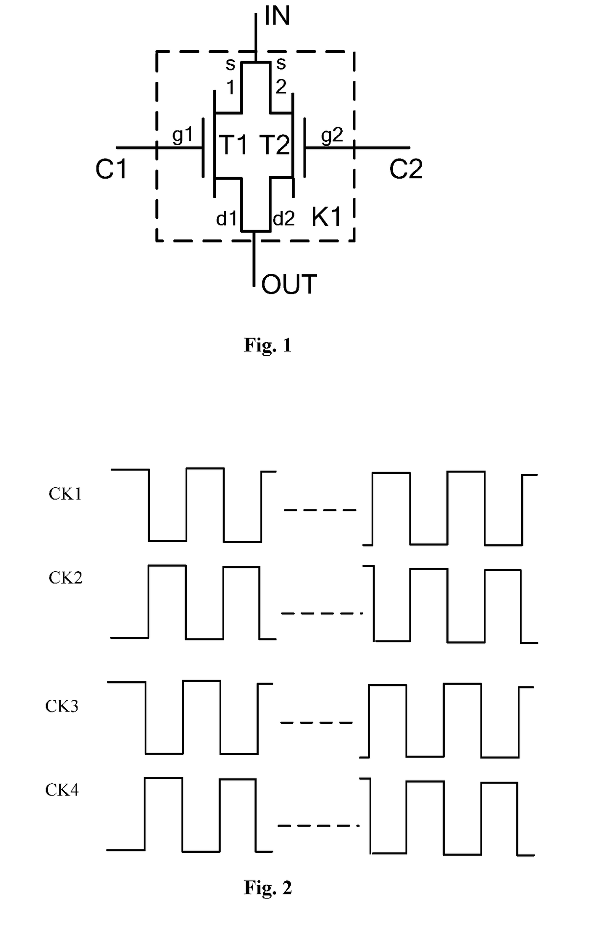
[0040]FIG. 1 is a structural diagram of a bidirectional selection unit in a GOA drive unit according to a specific embodiment of the present disclosure. As shown in FIG. 1, the bidirectional selection unit comprises a first switching element K1, which has a first control end C1, a second control end C2, a signal input end IN, and a signal output end OUT.

[0041]Furthermore, the first switching element K1 includes two parallel TFT devices. As shown in FIG. 1, a first thin film transistor T1 and a second thin film transistor T2 constitute two parallel transmission channels, respectively. A source s1 of T1 is connected to a source s2 of T2, serving as the signal input end IN of the first switching element K1. A drain d1 of T1 is connected to a drain d2 of T2, serving as the signal output end OUT of the first switching element K1. A gate g1 of T1 serves as the first control end C1 of the first switching element K1; and a gate g2 of T2 serves as the second control end C2 of the first switc...

embodiment 2

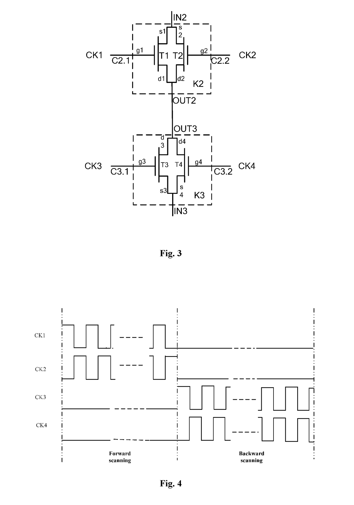
[0051]FIG. 3 is a structural diagram of a bidirectional selection unit in a GOA drive unit based on another embodiment of the present disclosure. As shown in FIG. 3, the bidirectional selection unit comprises a second switching element K2 and a third switching element K3. The second switching element K2 has a first control end C2.1, a second control end C2.2, a signal input end IN2, and a signal output end OUT2. The third switching element K3 has a first control end C3.1, a second control end C3.2, a signal input end IN3, and a signal output end OUT3.

[0052]Furthermore, each of the second switching element K2 and the third switching element K3 includes two parallel TFT devices. As shown in FIG. 3, the second switching element K2 comprises a first thin film transistor T1 and a second thin film transistor T2, which constitute two parallel transmission channels, respectively. A source s1 of T1 is connected to a source s2 of T2, serving as the signal input end IN2 of the second switching...


PUM


Abstract

Disclosed are a GOA drive unit and a GOA drive circuit. The GOA drive unit includes a bidirectional selection unit. The bidirectional selection unit is activated under an action of a first control signal and a second control signal which are complementary to each other in timing sequence, and outputs a first selection signal. The bidirectional selection unit is activated under an action of a third control signal and a fourth control signal which are complementary to each other in timing sequence, and outputs a second selection signal. The GOA drive unit can reduce the influence of stress and improve the reliability of the GOA drive circuit.

Description

CROSS-REFERENCE TO RELATED APPLICATIONS[0001]This application claims the priority of Chinese patent application CN 201710227247.0, entitled “GOA drive unit and GOA drive circuit” and filed on Apr. 11, 2017, the entirety of which is incorporated herein by reference.FIELD OF THE INVENTION[0002]The present disclosure relates to the field of display panel drive technologies, and in particular, to a GOA drive unit and a GOA drive circuit.BACKGROUND OF THE INVENTION[0003]Currently, GOA (Gate on array) drive technology has been widely applied in the drive of a display panel. A GOA drive circuit is used for successively outputting line scanning signals to respective pixel unit lines. When the display panel is driven, a forward scanning approach, which is from a first line of pixel units to a last line of pixel units, can be adopted, or a backward scanning approach, which is from the last line of pixel units to the first line of pixel units, can be adopted. Generally, in the GOA drive circui...

Claims


Application Information

Patent Timeline
IPC IPC(8): G09G3/20
CPCG09G3/20G09G2310/0213G09G2310/08G09G2300/0408G09G2300/0426G09G2300/0809G09G2310/0243G09G2310/0283
Inventor MA, WEIXIN
Owner WUHAN CHINA STAR OPTOELECTRONICS TECH CO LTD
Learn More