Low-energy-consumption and high-efficiency circulating electric motor

a circulating electric motor and low energy consumption technology, applied in the direction of dc interrupters, magnetic circuit shapes/forms/construction, transportation and packaging, etc., can solve the problems of low power efficiency, inability to greatly improve the efficiency of electric motors, and extremely limited rechargeable power, etc., to achieve the effect of high-efficiency circulating electric motors

Inactive Publication Date: 2019-03-21
WANG MENG THENG
View PDF10 Cites 1 Cited by
  • Summary
  • Abstract
  • Description
  • Claims
  • Application Information

AI Technical Summary

Benefits of technology

[0009]With the circulating electric motor provided by the present invention, since the fan simultaneously controls the DC electromagnet to intermittently generate a magnetic force during the continuous operation, and then pushes the fan to rotate at an appropriate time without being reversely interfered by the magnetic force. Therefore, the fan and its rotating-shaft can be driven to rotate with low energy consumption, and the rotation of the fan and the rotating-shaft can drive the generator to generate electric power to recharge the storage battery, thereby achieving the purpose of low-energy-consumption and high-efficiency circulating electric motor.

Problems solved by technology

Therefore, in addition to part of the electric energy used to drive the rotating shaft to work, another part of the electric energy is lost by mechanical friction and heat, such that the power efficiency is low.
However, based on the principle of energy non-extinction, the power that can be recharged is extremely limited, so the efficiency of the electric motor cannot be greatly improved.

Method used


Image

  • Low-energy-consumption and high-efficiency circulating electric motor
  • Low-energy-consumption and high-efficiency circulating electric motor
  • Low-energy-consumption and high-efficiency circulating electric motor

Examples


Embodiment Construction

[0015]The following descriptions are exemplary embodiments only, and are not intended to limit the scope, applicability or configuration of the invention in any way. Rather, the following detailed description provides a convenient illustration for implementing exemplary embodiments of the invention.

[0016]Various changes to the described embodiments may be made in the function and arrangement of the elements described without departing from the scope of the invention as set forth in the appended claims.

[0017]The foregoing and other aspects, features, and utilities of the present invention will be best understood from the following detailed description of the preferred embodiments when read in conjunction with the accompanying drawings.

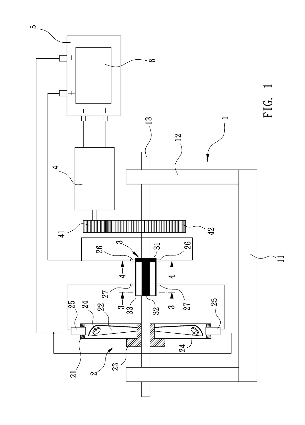
[0018]As shown in FIG. 1, the pedestal 1 preferably has a bottom-seat 11, which two stands 12 are erected on two opposite sides of the bottom-seat 11 and a rotating-shaft 13 is movably set between the two stands 12; wherein the embodiment of the present...


PUM


Abstract

A low-energy-consumption and high-efficiency circulating electric motor that a fan and a circular cylinder-body are disposed on a rotating-shaft and a permanent magnet is disposed on at least one blade of the fan, and at least a permanent magnet is disposed in a frame; wherein the outer diameter surface of the circular cylinder-body is set with a continuous circumferential conductive portion, and a plurality of axial conductive portions are lined in interval and connected with the circumferential conductive portion; wherein a DC generator is connected with the rotating-shaft and a storage battery is electrically connected with a control unit, the DC generator, the circumferential conductive portion, and the DC electromagnet; at the same time, the DC electromagnet intermittently generates a magnetic force by orderly contacting and not contacting the axial conductive portions; and the fan is continuously rotated by the intermittent magnetic force interacting with the permanent magnet.

Description

(a) TECHNICAL FIELD OF THE INVENTION[0001]The present invention relates to an electric motor, and in particular to a circulating electric motor that can operate with high efficiency and under low-energy consumption by the cooperated combination of the electric force and the magnetic force.(b) DESCRIPTION OF THE PRIOR ART[0002]Generally, the motor is driven by alternating current or direct current. Therefore, in addition to part of the electric energy used to drive the rotating shaft to work, another part of the electric energy is lost by mechanical friction and heat, such that the power efficiency is low.[0003]In order to improve the energy utilization efficiency, conventionally it is possible to electrically connect the storage battery and the power recharging device to the motor. And, the generator is driven to generate electricity and recharge into the storage battery for recycling usage while the motor is operating.[0004]However, based on the principle of energy non-extinction, ...

Claims


Application Information

Patent Timeline
Patent Type & Authority Applications(United States)
IPC IPC(8): H02K53/00H02K1/06H02J7/14
CPCH02K53/00H02K1/06H02J7/14H02K25/00
Inventor WANG, MENG-THENG
Owner WANG MENG THENG
Why Eureka
Try Eureka