Method for determining a load current and battery sensor

a load current and battery technology, applied in the field of method for determining a load current and battery sensor, can solve the problems of high and temporally greatly variable currents, continuous recalibration even while, high cost, etc., and achieve high resistance, high cost-effectiveness, and high accuracy of current measurement.

Active Publication Date: 2019-03-28
CONTINENTAL AUTOMOTIVE GMBH
View PDF28 Cites 1 Cited by
  • Summary
  • Abstract
  • Description
  • Claims
  • Application Information

AI Technical Summary

Benefits of technology

[0085]The described arrangement and the described method make it possible to determine the load current practically without prior knowledge of the resistor network or the group of measuring resistors and the relative accuracy of the measuring devices used to measure the voltages. As a result, despite the more cost-effective material, it is even possible to achieve a higher accuracy of the current measurement than in embodiments according to the prior art. This is because substantially both the tolerance of the resistance value of the measuring resistor and the tolerance of the voltage measuring apparatus for the voltage drop were previously included in the tolerance of the measured current value.
[0086]Typically, only accurate knowledge of Iref at one time is required with the apparatus or arrangement described. In addition, virtually no demands are imposed on the quality of the current source for Iref. Only an accurate measurement of Iref is typically required. This can be easily achieved, for example, with an accordingly accurate reference resistor Rref and an accurate measurement of the voltage drop across Rref. This is because, unlike the measuring resistor for the load current, Rref can have a high resistance of 1 ohm, for example, which needs to be designed only for small reference currents and not for high load currents. As a result of the value of Rref which is accordingly selected to be high, the voltage drop Iref*Rref can also be conveniently measured since there is no need for a complicated amplifier, for example.

Problems solved by technology

The disadvantages of the previous embodiments are, in particular, the high costs, in particular for creating resistor materials which have more or less constant resistance values in a conventional temperature range of −40° C. to 105° C., for example.
However, it has been found that continuous recalibration even while simultaneously measuring the high and temporally greatly variable currents occurring in the motor vehicle is difficult under the prevailing boundary conditions, in particular a desired low power consumption of the sensor, since the calibration current to be applied for calibration is intended to be selected to be small and is intended to be applied only briefly.

Method used


Image

  • Method for determining a load current and battery sensor
  • Method for determining a load current and battery sensor
  • Method for determining a load current and battery sensor

Examples


Embodiment Construction

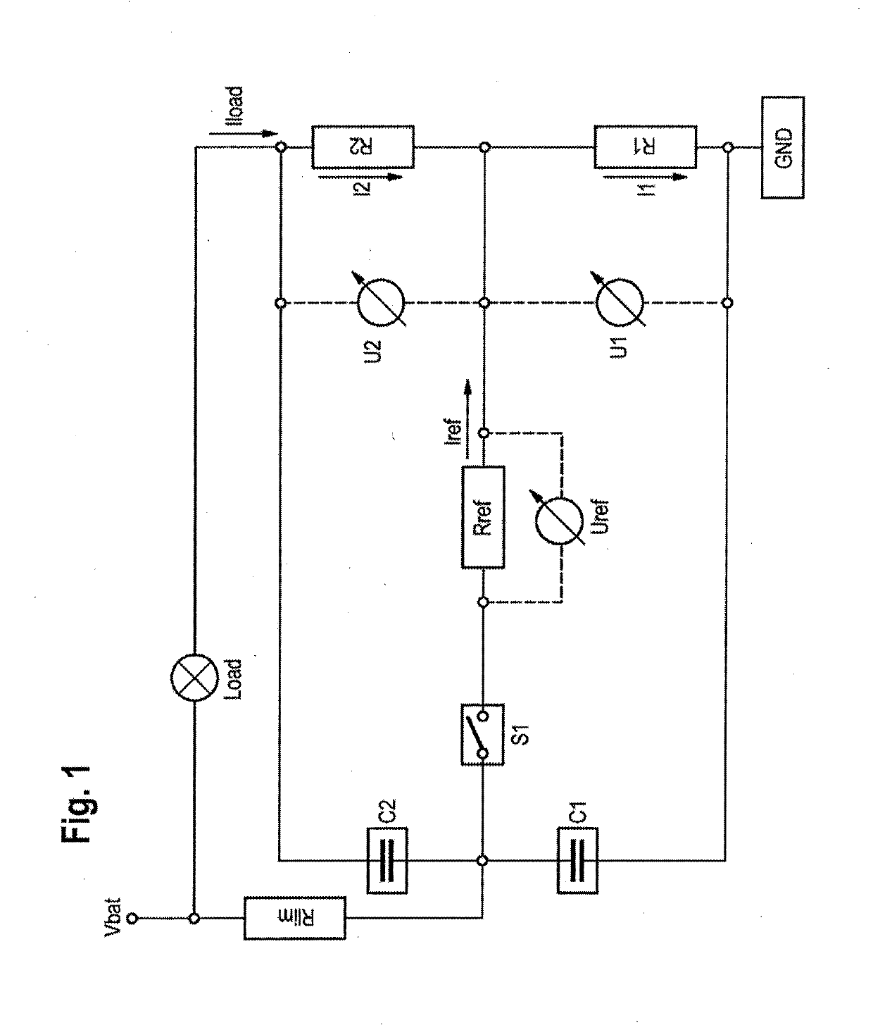
[0094]FIG. 1 shows a group of measuring resistors with connection according to a first exemplary embodiment which can also be advantageously used to carry out the method according to an aspect of the invention.

[0095]The group of measuring resistors has a first measuring resistor R1 and a second measuring resistor R2, via which a temporally variable load current Iload is conducted. This load current Iload initially comes from a battery which is depicted, in terms of voltage, as Vbat in FIG. 1. The load current Iload also flows via a load which is generally referred to as Load and is only schematically illustrated here and may comprise typical electrical components of a motor vehicle, for example a starter motor, a vehicle light or electronic components as well as a generator.

[0096]A first voltmeter U1 is arranged across the first measuring resistor R1. A second voltmeter U2 is arranged across the second measuring resistor R2. These are designed to measure respective voltages across t...


PUM


Abstract

The invention relates to a method for determining a load current, which is based on conducting a calibration current in a particular manner and on particular calculation methods.

Description

CROSS REFERENCE TO RELATED APPLICATIONS[0001]This application is the U.S. National Phase application of PCT International Application No. PCT / EP2017 / 056610, filed Mar. 21, 2017, which claims priority to German Patent Application No. 10 2016 206 958.6, filed Apr. 25, 2016, the contents of such applications being incorporated by reference herein.FIELD OF THE INVENTION[0002]The invention relates to a method for determining a load current flowing through a group of measuring resistors.BACKGROUND OF THE INVENTION[0003]Such a method can be used, in particular, to determine the battery condition of a battery, for example an automobile battery. In order to determine a battery condition, it is typically necessary to measure the battery current. This can also be referred to as the load current. For this purpose, highly accurate resistors or sensors are typically used to measure the magnetic field strength in embodiments according to the prior art. The disadvantages of the previous embodiments...

Claims


Application Information

Patent Timeline
Patent Type & Authority Applications(United States)
IPC IPC(8): G01R31/36G01R1/20G01R35/00
CPCG01R31/3835G01R1/203G01R35/005G01R15/146
Inventor AUMER, ANDREASGRAF, HANS-MICHAELSCHRAMME, MARTIN
Owner CONTINENTAL AUTOMOTIVE GMBH
Why Eureka
Try Eureka