
Driving around-view auxiliary device

Inactive Publication Date: 2019-04-04
HUA CHUANG AUTOMOBILE INFORMATION TECHN CENT
View PDF8 Cites 3 Cited by
  • Summary
  • Abstract
  • Description
  • Claims
  • Application Information

AI Technical Summary

Benefits of technology

The present invention is about a device that allows drivers to see the world around their vehicle through a camera and display. The device uses technology to delay and display the images, making it easy to see the road conditions beneath the vehicle. The technical effect of this invention is to provide drivers with a better view of their surroundings, improving safety and efficiency.

Problems solved by technology

Therefore, the conventional technologies still merely resolve requirements on fields of view of a vehicle exterior around view.
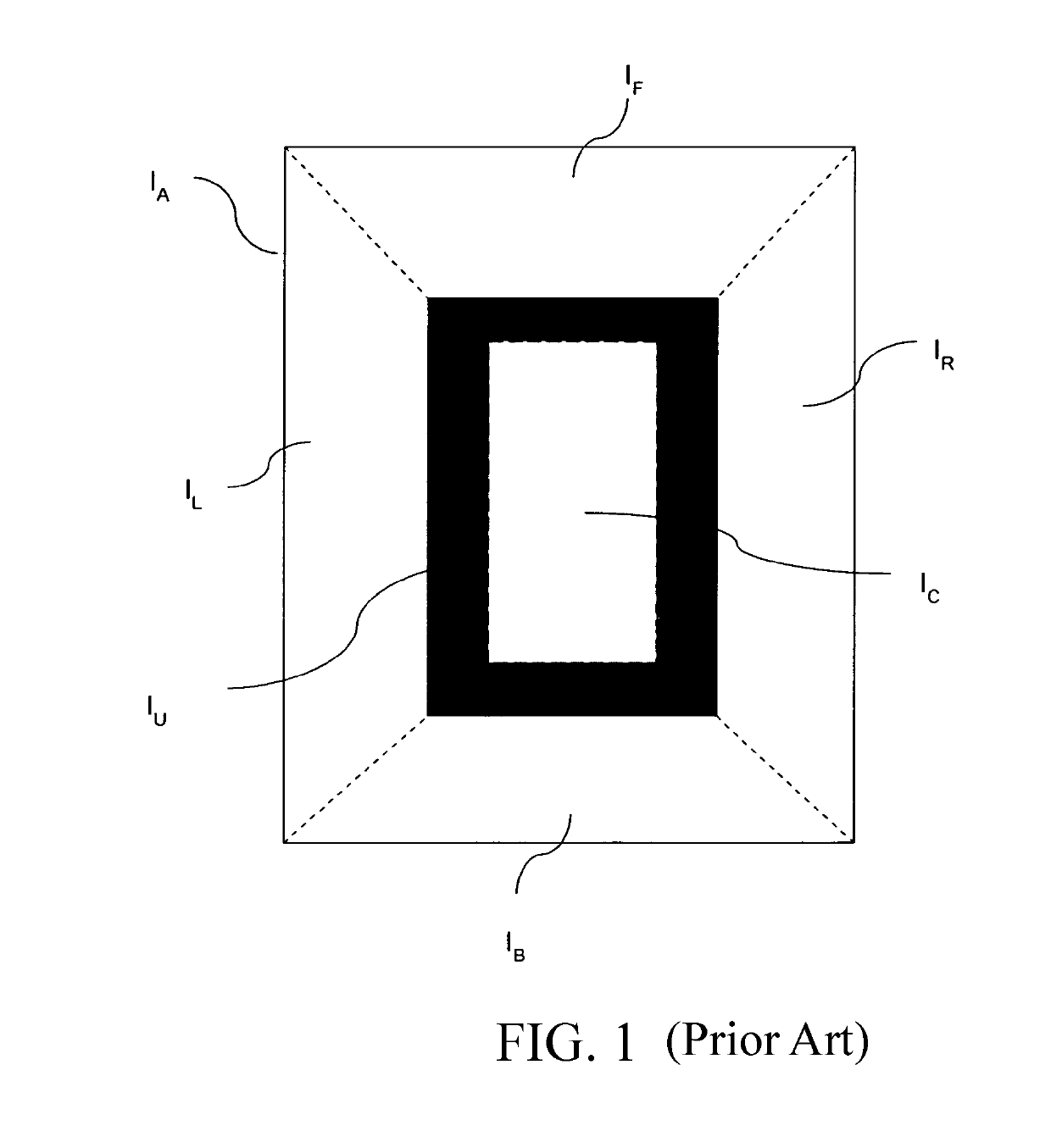
However, the under-vehicle image IU processed by using a black image cannot enable the driver to see clearly the road condition under the vehicle floor, and matters for regret such as: a vehicle wheel falls into a ditch or a little animal under the vehicle is mistakenly crushed may occur to the driving.

Method used


Image

  • Driving around-view auxiliary device
  • Driving around-view auxiliary device
  • Driving around-view auxiliary device

Examples


Embodiment Construction

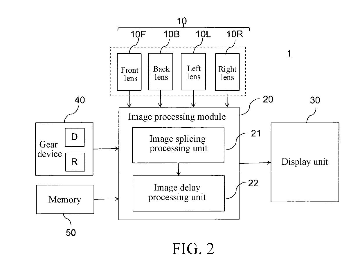
[0011]Referring to FIG. 2, FIG. 2 is a block diagram of a driving around-view auxiliary device according to the present invention. In this embodiment, a driving around-view auxiliary device 1 is applicable to a vehicle. The device mainly includes a lens group 10, an image processing module 20, and a display unit 30. The lens group 10 includes a plurality of lenses, where these lenses are respectively disposed at different positions around the vehicle, to respectively capture a plurality of external images around the vehicle. Using this embodiment as an example, the lens group 10 includes a front lens 10F, a back lens 10B, a left lens 10L, and a right lens 10R, separately. The image processing module 20 is electrically connected to the lens group 10, and includes an image splicing processing unit 21 and an image delay processing unit 22. The display unit 30 is electrically connected to the image processing module 20, and is configured to output and display an image.

[0012]Referring to...


PUM


Abstract

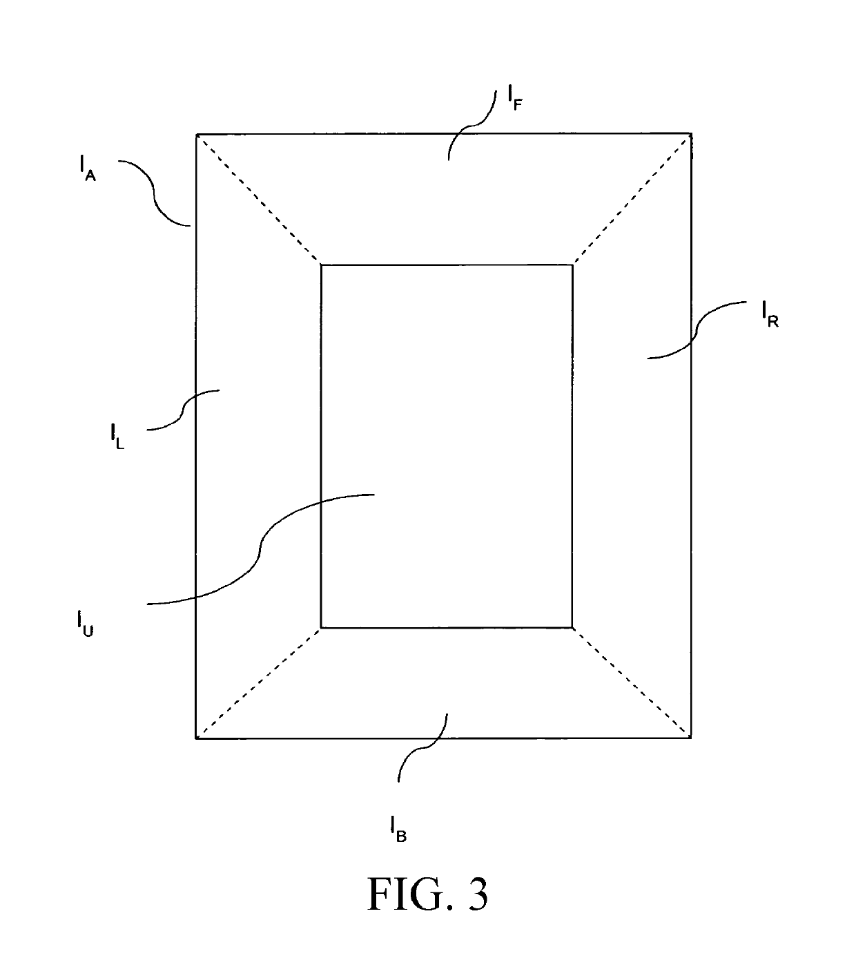
A driving around-view auxiliary device includes a lens group, an image processing module, and a display unit. The lens group can capture a plurality of external images around the vehicle. The image processing module includes an image splicing processing unit and an image delay processing unit. The image splicing processing unit can splice the foregoing external images into a vehicle exterior around-view image. The image delay processing unit is capable of dividing, according to a travel path of the vehicle, the vehicle exterior around-view image that overlaps the travel path into a plurality of delayed images, and sequentially attaching, according to a delay time and starting from the delayed image that is adjacent to the under-vehicle image, the delayed images on an under-vehicle image segmented in the vehicle exterior around-view image. The display unit displays the vehicle exterior around-view image and a total perspective image formed by the under-vehicle image.

Description

BACKGROUNDTechnical Field[0001]The present invention relates to a driving around-view auxiliary device, and in particular, to a driving around-view auxiliary device that can view a road condition through the vehicle floor.Related Art[0002]In the past, in a driving process, whether there are obstacles can be viewed only with assistance of internal and external rearview mirrors. Safeties of the internal and external rearview mirrors are widely castigated because the internal and external rearview mirrors have innate dead angles. As the development of technologies of image identification, a driver can easily view a road condition outside the vehicle by splicing and synthesizing images into a top-view around-view image by using a plurality of lenses (usually are a front lens, a back lens, a right lens, and a left lens), and playing the around-view image through a screen.[0003]Referring to FIG. 1, FIG. 1 is a schematic diagram of a conventional driving around view. After the foregoing fr...

Claims


Application Information

Patent Timeline
IPC IPC(8): B60L3/12G06T1/00
CPCB60L3/12G06T1/0007B60L2250/16B60Y2400/3015B60Y2400/92G06T2200/32G06T3/4038
Inventor CHEN, YONG-JHOUCHEN, LE-HUNGCHAN, MENG-HUNG
Owner HUA CHUANG AUTOMOBILE INFORMATION TECHN CENT
Learn More