Driving belt and manufacturing method thereof

a technology of driving belts and manufacturing methods, applied in the direction of belts/chains/gearings, v-belts, mechanical devices, etc., can solve the problems of difficult to engage the last piece of the element with the hoop without damaging the elements and the hoop, and achieve the effect of easy assembly and fitting with the hoop

Inactive Publication Date: 2019-04-04
TOYOTA JIDOSHA KK
View PDF0 Cites 8 Cited by
  • Summary
  • Abstract
  • Description
  • Claims
  • Application Information

AI Technical Summary

Benefits of technology

[0016]In addition, according to the manufacturing method of the present disclosure, the last piece of the element may be fitted eas

Problems solved by technology

However, there is almost no clearance between the adjacent elements in the final phase of the assembling work in which the pins of each of the elements are individually fitted into the holes of the adjacent elements.
Therefore, the last piece of th

Method used


Image

  • Driving belt and manufacturing method thereof
  • Driving belt and manufacturing method thereof
  • Driving belt and manufacturing method thereof

Examples


Embodiment Construction

)

[0027]Embodiments of the present disclosure will now be explained with reference to the accompanying drawings. Note that the embodiments shown below are merely examples of cases where the present disclosure has been actualized, and do not limit the present disclosure.

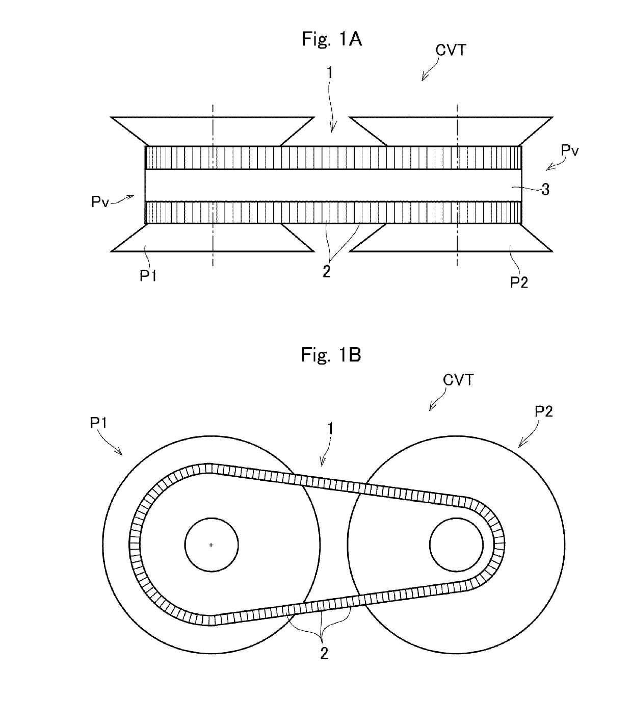
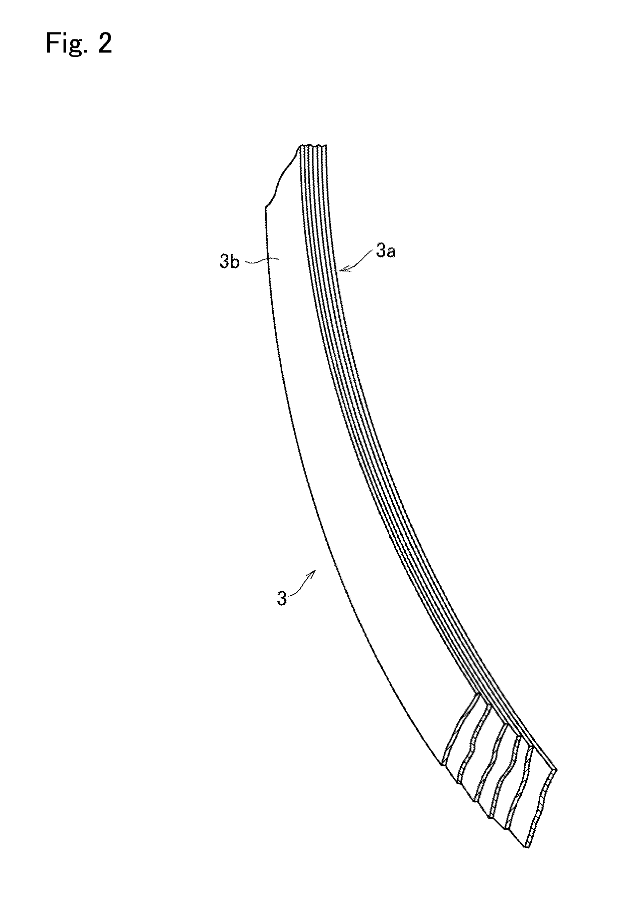
[0028]A driving belt 1 according to the embodiment of the present disclosure is employed as a V belt of a belt-driven continuously variable transmission (to be abbreviated as the “CVT” hereinafter) installed in a vehicle to transmit power between two pulleys. Specifically, as shown in FIGS. 1A and 1B, the driving belt 1 is wound on respective pulley grooves Pv of a drive pulley P1 and a driven pulley P2 of the CVT. The driving belt 1 is a so-called a “push belt” in which a plurality of thin metal elements 2 are juxtaposed in a same orientation, and the elements 2 are fastened in loop form by a hoop 3. In the CVT, the elements 2 sequentially enter into the pulley grooves Pv of the drive pulley P1 and the driven pulley P...


PUM


Abstract

A driving belt in which elements may be engaged easily with a hoop, and a manufacturing method thereof. Element includes a first element as a standard element and a second element to be inserted between the adjacent first elements in a final phase of assemble. The second element includes a second saddle surface, and pillars erected on each width end of the second saddle surface. An opening width between the pillars is wider than the width of the hoop. The second element is provided with at least one of a second boss fitted into the first dimple of the first element, and a second dimple fitted onto the first boss of the first element.

Description

CROSS REFERENCE TO RELATED APPLICATIONS[0001]The present disclosure claims the benefit of Japanese Patent Application No. 2017-190690 filed on Sep. 29, 2017 with the Japanese Patent Office, the disclosure of which is incorporated herein by reference in its entirety.BACKGROUNDField of the Disclosure[0002]Embodiments of the present disclosure relate to the art of a driving belt used in a transmission device such as a continuously variable transmission (referred to as CVT hereinafter), and a method for manufacturing the belt.Discussion of the Related Art[0003]JP-T-2017-516966 describes one example of a driving belt such as a push belt. The belt taught by JP-T-2017-516966 is configured by arranging several hundreds of metal elements (or blocks) with their postures aligned and binding the elements in loop form by the hoop (or carrier or ring). The belt thus formed is applied to a pair of pulleys in which running diameters of the belt in the pulleys may be changed arbitrarily. Each of the...

Claims


Application Information

Patent Timeline
IPC IPC(8): F16G5/16
CPCF16G5/16F16G5/22
Inventor NINOMIYA, KEISUKE
Owner TOYOTA JIDOSHA KK
Why Eureka
Try Eureka