Male insert for draining fluid from a patient

a technology for draining fluid and patients, applied in the field of surgical drains, can solve the problems of reducing patient mobility, encumbrance of ambulation, and pressure felt by physicians to remove drains prematurely, and achieve the effect of preventing pivotal movement and preventing rotational movement of the tub

Active Publication Date: 2019-04-11
KIRN MEDICAL DESIGN
View PDF4 Cites 1 Cited by
  • Summary
  • Abstract
  • Description
  • Claims
  • Application Information

AI Technical Summary

Benefits of technology

[0026]In still another possible embodiment, movement of the locking ring from the extended position to the retracted position moves the surface of the locking ring preventing rotation movement of the tube allowing rotational movement of the tube.
[0027]In yet another possible embodiment, the male insert further includes a tab preventing rotational movement of the tube when the valve stem is in the retracted position. In still yet another possible embodiment, the male insert further includes a tab preventing pivotal movement of the valve stem when the valve stem is in the retracted position.

Problems solved by technology

While the above surgical drains and methods are simple and time tested, they have several limitations including, for example, difficulty concealing and fitting clothing around the external tube and reservoir, encumbered ambulation and thereby retarded and diminished patient mobility, a need to periodically empty the reservoir, a need to periodically reset the reservoir to keep suction on the system, discomfort for the patient due to traction on the external tubing and reservoir, patient compliance with using the drain appropriately and recording drainage output, pressure felt by physicians to remove drains prematurely because of patient complaints, risk of infection from manipulation of the drain during regular operation and the presence of a static external to internal conduit, the risk of body fluids escaping the reservoir if the reservoir plug comes loose, the exposure of the nurse or caretaker to the patient's body fluid when emptying the reservoir, ease of dislodgment of the drain due to a large external extension and difficulty replacing once removed, designs necessitating continuous evacuation, and single use functionality.

Method used


Image

  • Male insert for draining fluid from a patient
  • Male insert for draining fluid from a patient
  • Male insert for draining fluid from a patient

Examples


Embodiment Construction

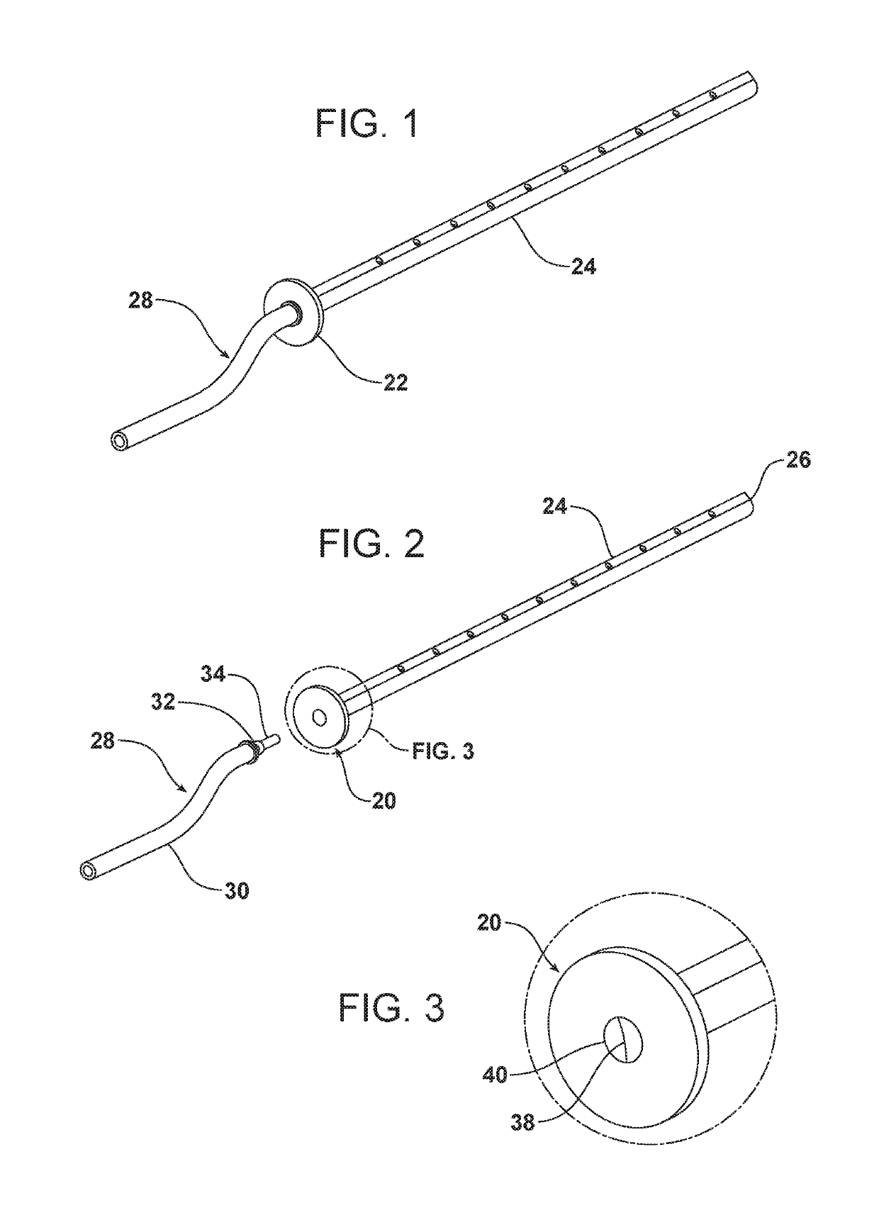
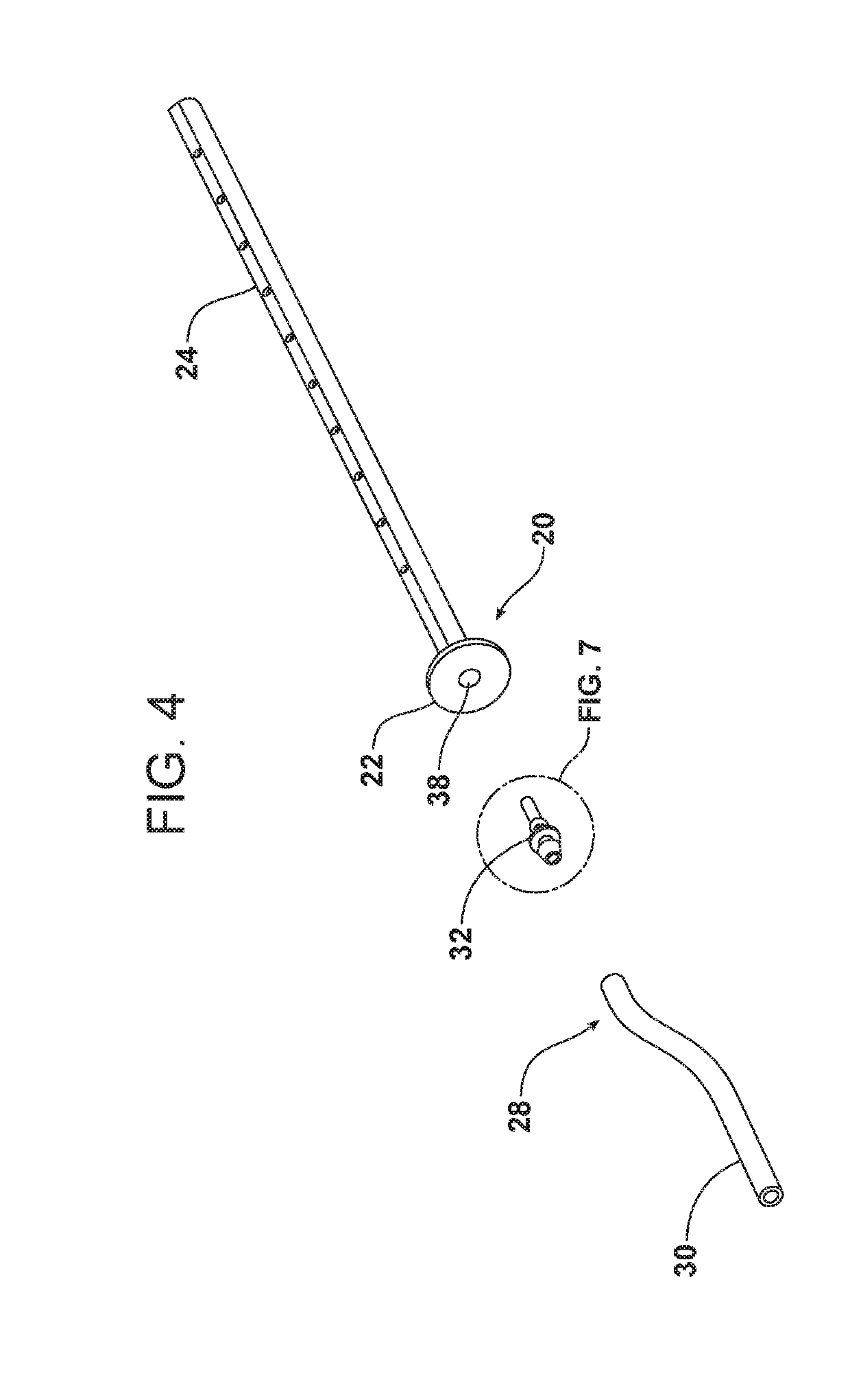
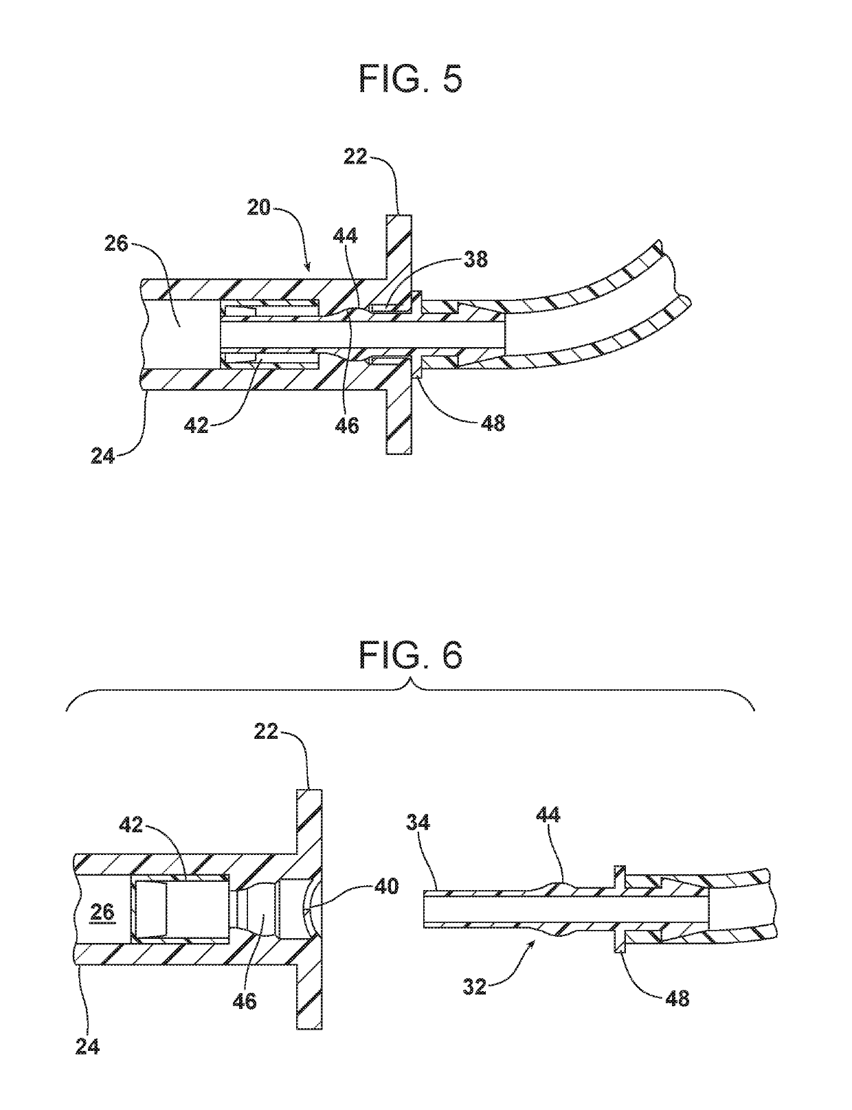
[0058]Reference is now made to FIGS. 1 and 2 which illustrate an embodiment of a surgical drain system. The surgical drain system includes an adapter 20 having a flange 22, and drain tube 24 which passes through an incision in the patient's skin. Thus, drain tube 24 is primarily contained internally within the patient's body. An interior face of the flange 22 rests adjacent to the patient's skin surface when the drain tube 24 is inserted into the patient. Suture material may be passed through flange 22 to secure it in place. Alternatively, the flange 22 could contain a hole for suture material to pass through or an anchor post.

[0059]In the present described embodiment, the drain tube 24 is integrally formed with the adapter 20 so that they form one continuous, uniform unit. The drain tube 24 includes a distal end, adjacent the flange 22, and a proximal end which extends into the body cavity to be drained. Along a portion of the proximal portion of the drain tube 24, the tube include...


PUM


Abstract

A male insert for draining fluid from a patient is provided. The male insert includes a housing, a valve stem supported by the housing for pivotal movement about an axis from an extended position allowing insertion into the patient to a retracted position preventing re-insertion into the patient, a tube connected to the valve stem and supported by the housing for rotational movement about the axis, the tube and the valve stem forming a contiguous channel through which the fluid drains, a stop preventing rotational movement of the tube in a first position and allowing rotational movement of the tube in a second position, and a locking tab engaging one of the valve stem and the tube when the valve stem is in the retracted position.

Description

TECHNICAL FIELD[0001]This document relates generally to surgical drains, and more specifically to a male insert for draining fluid from a patient.BACKGROUND[0002]Surgical drains have been in use for many years and are an industry standard. Most modern surgical drains are closed suction drains in which a flexible tube, usually silicone, is placed into the surgical space. Holes or slots in the tube allow fluid egress into the lumen of the tube. The tube extends external to the body via an opening in the skin. Externally, a variable length of tubing is connected to a reservoir. The reservoir collects the body fluid exiting the drain and may also be used to generate suction to aid in fluid evacuation.[0003]While the above surgical drains and methods are simple and time tested, they have several limitations including, for example, difficulty concealing and fitting clothing around the external tube and reservoir, encumbered ambulation and thereby retarded and diminished patient mobility, ...

Claims


Application Information

Patent Timeline
Patent Type & Authority Applications(United States)
IPC IPC(8): A61M27/00A61M39/24
CPCA61M27/00A61M39/24A61M39/12A61M39/26A61M2039/2426A61M1/82A61M1/86A61M1/84
Inventor MARSICO, BENATASHROO, DAVID A.KIRN, DAVID S.
Owner KIRN MEDICAL DESIGN
Why Eureka
Try Eureka