Support member for additive manufacturing, production method and production device for three-dimensional object by additive manufacturing, manufactured object model creation device, control device, and manufacturing method for manufactured object

a technology of manufacturing method and manufacturing method, which is applied in the direction of additive manufacturing, process efficiency improvement, and additive manufacturing apparatus, etc., can solve the problems of not being able to add a layer in an appropriate shape, not being able to ensure the shape accuracy of a three-dimensional object to be manufactured, and not being able to appropriately manufacture layers. to achieve the effect of easy removal of the support for additive manufacturing

Active Publication Date: 2019-04-11
MITSUBISHI HEAVY IND LTD
View PDF0 Cites 3 Cited by
  • Summary
  • Abstract
  • Description
  • Claims
  • Application Information

AI Technical Summary

Benefits of technology

[0036]According to at least one of the above aspects, it is possible for the support for additive manufacturing disposed below the manufactured portion having a condition that it needs a support to secure the shape accuracy of the three-dimensional object when the three-dimensional object is additively manufactured.
[0037]Also, after manufacturing, the support for additive manufacturing can be removed by passing a fluid through the channel inside the support main body. Since the fluid can be passed using a machine, it is possible to easily remove the support for additive manufacturing.
[0038]Since the channel is formed not to be exposed at the interface with the three-dimensional object inside the support main body, it is difficult for the fluid to directly pass along the surface of the three-dimensional object and it is possible to prevent the surface of the three-dimensional object from being cut and damaged with the fluid.

Problems solved by technology

Thus, it is not possible to add a layer in an appropriate shape and it is not possible to secure the shape accuracy of a three-dimensional object to be manufactured.
However, when there is an overhanging portion in the layers to be added (here, a ninth layer or more), it is not possible to appropriately manufacture the layers if there is no support member below the layers [refer to FIG. 14(c)].

Method used


Image

  • Support member for additive manufacturing, production method and production device for three-dimensional object by additive manufacturing, manufactured object model creation device, control device, and manufacturing method for manufactured object
  • Support member for additive manufacturing, production method and production device for three-dimensional object by additive manufacturing, manufactured object model creation device, control device, and manufacturing method for manufactured object
  • Support member for additive manufacturing, production method and production device for three-dimensional object by additive manufacturing, manufactured object model creation device, control device, and manufacturing method for manufactured object

Examples


first embodiment

(Constitution of Support Member for Additive Manufacturing)

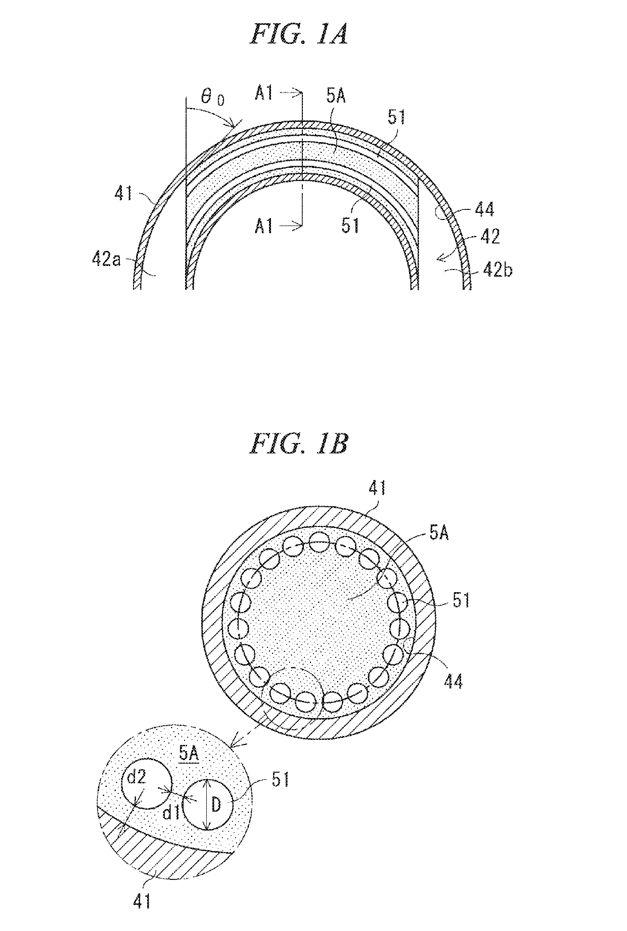
[0072]As illustrated in FIG. 3, the three-dimensional object 4A according to this embodiment includes a tubular portion 41 in a part thereof, the tubular portion 41 having a tubular channel (tubular channel space) 42 as a closed cross-sectional-shaped space inside thereof. The tubular channel 42 has its axial center formed in a circular arc shape, has one end side 42a and the other end side 42b which are steeply inclined, and has an intermediate portion which is gently inclined. A portion corresponding to the particular overhanging portion to be supported by the support is present on an upper wall portion located vertically above a portion whose inclination is gentle at the intermediate portion of the tubular channel 42.

[0073]FIGS. 4A and 4B are diagrams for explaining the particular overhanging portion in the tubular portion 41. As illustrated in FIGS. 4A and 4B, a region of an upper tubular wall portion in the tubular port...

second embodiment

(Constitution of Support Member for Additive Manufacturing)

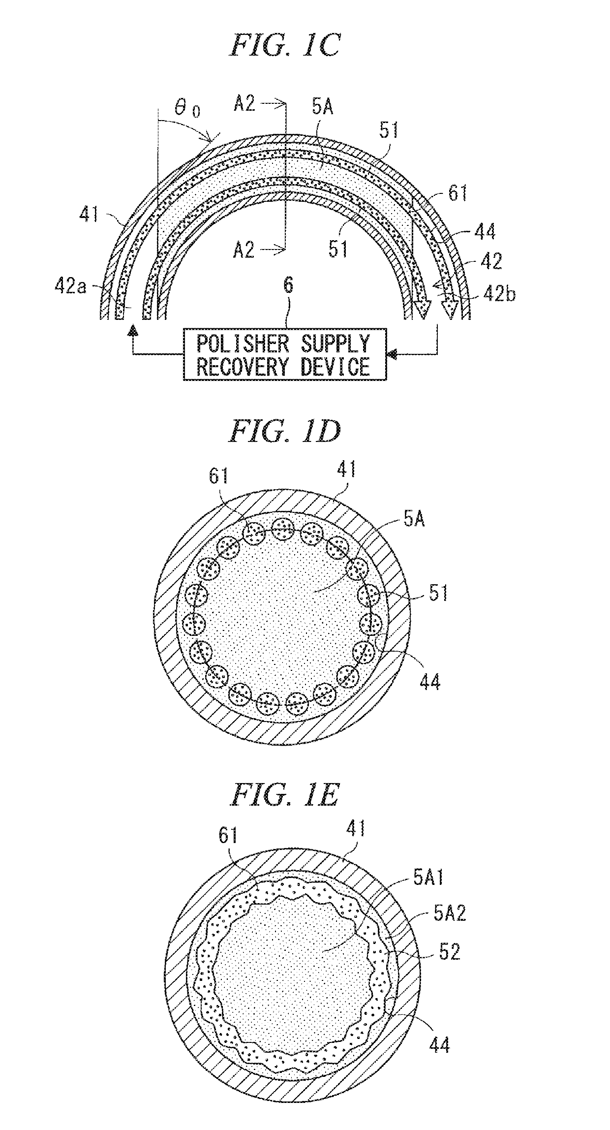
[0097]As illustrated in FIG. 5, a support 5B for additive manufacturing according to this embodiment is configured by attaching a first channel control support 53 and a second channel control support 54 for controlling a flow of a polisher to the support for additive manufacturing according to the first embodiment (which is set to a support main body) 5A.

[0098]The polishing channel 51 includes an inlet 51a which opens to a space on the one end side 42a of the tubular channel 42 and an outlet 51b which opens to a space on the other end side 42b of the tubular channel 42. The first channel control support 53 is disposed adjacent to a location in which the support main body 5A in the space on the one end side 42a is formed. Furthermore, the second channel control support 54 is disposed adjacent to a location in which the support main body 5A in the space on the other end side 42b is formed.

[0099]The first channel control suppor...

third embodiment

(Constitution of Support Member for Additive Manufacturing)

[0109]As described in FIG. 6, a three-dimensional object (not shown) according to this embodiment includes a tubular portion 41C having a tubular channel with a minute inner diameter. A support 5C for additive manufacturing is formed in at least a part of a tubular channel inside the tubular portion 41C. Since the inner diameter of the tubular channel is minute, only one polishing channel 51C is formed on an axial center portion of the tubular channel. Of course, an inner diameter of the polishing channel 51C is set to be the reference diameter or less.

(Action and Effect of Support Member for Additive Manufacturing)

[0110]In this way, since a support 5C for additive manufacturing is formed, when the support 5C is polished and removed, the support 5C is polished by allowing the polishing fluid to pass through the polishing channel 51C formed in the axial center portion as in the first embodiment. Since an inner wall of the tub...


PUM

PropertyMeasurementUnit
overhanging angleaaaaaaaaaa
reference angleaaaaaaaaaa
diameter D0aaaaaaaaaa

Abstract

This support member for additive manufacturing is a support to be disposed below a manufactured portion of a particular overhanging portion of the three-dimensional object which needs the support in the process of additively manufacturing the three-dimensional object. The support member is provided with: the support main body; and a polishing channel which is formed in the support main body so as not to be exposed to an interface with the three-dimensional object, and through which a polisher for polishing and removing the support main body is allowed to pass.

Description

TECHNICAL FIELD[0001]The present invention relates to a support member for additive manufacturing, a production method and a production device for a three-dimensional object by additive manufacturing, a manufactured object model creation device, a control device, and a manufacturing method for a manufactured object.[0002]Priority is claimed on Japanese Patent Application No. 2016-080538, filed Apr. 13, 2016, and Japanese Patent Application No. 2017-029060, filed Feb. 20, 2017, the content of which are incorporated herein by reference.BACKGROUND ART[0003]In recent years, additive manufacturing methods for additively manufacturing a three-dimensional object (3D additive manufacturing methods) have been being developed. Such additive manufacturing methods include various methods such as, for example, powder bed laser lamination welding (selective laser melting, SLM). An additive manufacturing method in the field of metal manufacturing (a so-called metal additive manufacturing method) h...

Claims


Application Information

Patent Timeline
Patent Type & Authority Applications(United States)
IPC IPC(8): B22F3/105B33Y10/00B33Y30/00B33Y50/02B22F3/24B33Y70/00
CPCB22F3/1055B33Y10/00B33Y30/00B33Y50/02B22F3/24B33Y70/00B22F2003/1058B22F2003/247B22F2999/00Y02P10/25B22F10/28B22F10/47B22F10/80B22F10/66B33Y40/20B22F5/10B22F10/00
Inventor KAMITANI, KEISUKEOGAWA, NAOKIKUGA, KAZUNORIKYUNO, HIROAKI
Owner MITSUBISHI HEAVY IND LTD
Why Eureka
Try Eureka