Simplified pitch actuation system for a turbomachine propeller

Active Publication Date: 2019-04-11
SN DETUDE & DE CONSTR DE MOTEURS DAVIATION S N E C M A
3 Cites 2 Cited by

AI-Extracted Technical Summary

Problems solved by technology

The failure resulting from the axial locking of the hydraulic cylinder (pro...

Method used

[0063]The actuation system 22 further comprises at least one sensor 46 of the LVDT type (acronym for Linear Variable Differential Transformer). In the example shown, the transmission screw 26 comprises an internal axial bore in which is slidably engaged a LVDT ferromagnetic plunger 46a carried by a rear cover 48 of the actuator 22, which is itself fixed to the stator casing 32. Although this is not shown, the plunger 46a is surrounded by several windings carried by the transmission screw 26, including at least one primary winding supplied by an alternating current and two secondary windings. These windings are preferably redundant to increase the reliability of the system. The axial displacement of the plunger 46a inside the windings, channels the flow and generates voltages in the secondary windings whose amplitudes depend on the position thereof. The sensor 46 thus provides a voltage proportional to the displacement of the plunger 46a.
[0065]The use of an electromechanical system for feathering offers the following advantages: the control box is simple and of high reliability; the case of short-circuiting does not need to be covered, it is not necessary to oversize synchronous machines to cover this case of failure; in the absence of short-circuiting induced by this engine, the rotor can be mounted directly on the rotor axis of the synchronous machines ...

Benefits of technology

[0028]Advantageously, said first means comprise two electric engines, preferably synchronous, driving the same first rotor. The choice of the technology and the strategy of the sizing of these electrical means allows to minimize the short-circuiting torque and to arrive at reasonable engine sizes. Electric redundancy of the electric engines allows to respect the FHA reliability requirements (problem A). To preserve a simple architecture, it is proposed here to make the rotors of electric engines common. This makes it possible to keep only one transmission chain and to have a relatively compact system. The proposed concept offers this advantage.
[0029]The proposed system is preferably able to provid...

Abstract

A pitch actuating system for a turbomachine propeller including an actuator having a movable portion configured to be connected to propeller blades for displacement thereof in rotation with respect to the pitch axes of the blades. A first pitch control means for the blades includes a first transmission screw movable in rotation, a first nut traversed by said first transmission screw and configured to cooperate with the blades for their displacement, second means for feathering the blades, which comprise a second fixed transmission screw, a second nut traversed by said second transmission screw and movable in translation on said second nut, and wherein the system is configured so that a translational movement of the second nut causes a translational movement of the first transmission screw.

Application Domain

PropellersEngine fuctions +4

Technology Topic

Pitch controlBlade pitch +2

Image

  • Simplified pitch actuation system for a turbomachine propeller
  • Simplified pitch actuation system for a turbomachine propeller
  • Simplified pitch actuation system for a turbomachine propeller

Examples

  • Experimental program(1)

Example

[0044]The invention will be better understood and other details, characteristics and advantages of the invention will emerge more clearly on reading the following description given by way of nonlimiting example and with reference to the appended drawings in which:
[0045]FIG. 1 is a partial schematic half-view in axial section of a blade pitch actuating system associated with a turbomachine propeller;
[0046]FIG. 2 is a block diagram showing the general architecture of the actuating system and the electrical control means of the system of FIG. 1;
[0047]FIG. 3 is a partial schematic half-view in axial section of a blade pitch actuation system according to the invention associated with a turbomachine propeller; and
[0048]FIGS. 4a to 7b are diagrams illustrating the operation of the system of FIG. 3, in several distinct cases.
DETAILED SPECIFICATION
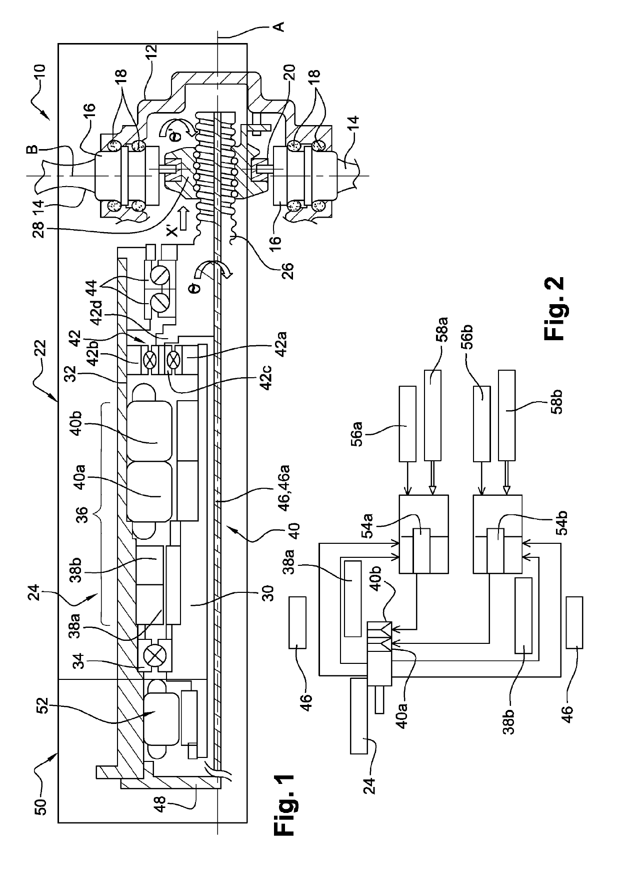
[0049]We first refer to FIG. 1.
[0050]A propeller 10 of a turbomachine, and in particular a turboprop, is generally unsheathed and comprises a movable hub 12 (arrow θ′ of FIG. 1) with axis A of rotation, the hub carrying blades 14 which extend substantially radially relative to the axis A. Each blade 14 is connected at its radially inner end to a substantially cylindrical plate 16 for supporting and guiding the blade in rotation in order to set its rotation about an axis B, in this case substantially radial. The plate 16 of each blade 14 is mounted in a housing of the hub 12 and is centered and guided in this housing by bearings 18 extending around the axis B. The radially inner end of each blade comprises an eccentric 20. The latter is integrally connected to the plate 16 and an actuating system 22 can move it in rotation about the axis B. The displacement of the eccentrics 20 causes a rotational movement of the plates 16 and therefore the blades 14 about the axes B. Each blade 14 can be set at a given pitch or in a given position about its axis B, between two extreme positions, one of which, called feathered, corresponds to the case where the chord of the cross section of the blade extends substantially parallel to the axis A.
[0051]In the prior art, the actuation system was hydraulic, and had many disadvantages. FIG. 1 shows an electromechanical actuation system.
[0052]The actuating system 22 of FIG. 1 comprises an electromechanical actuator 24 whose movable portion comprises a transmission screw 26 which is associated with a nut 28 guided in translation relative to the hub 12 and configured to cooperate with the eccentrics 20 of the blades 14 for their rotation in relation to the B axis.
[0053]The nut 28 comprises housings intended to receive the eccentrics 20 and to drive them during the displacements of the nut 28. Each housing receives, for example, an eccentric finger 20 of the corresponding blade 14, each finger being disposed in a protruding position into the housing. The nut is thus integral with the blades while in movement, and therefore to the propeller when the latter is rotated relative to the axis A. The nut 28 is thus arranged to be rotatable relative to the axis A in a fixed reference.
[0054]The transmission screw 26 extends along the axis A and is rotatable relative to the axis A. It passes through the nut 28 and therefore comprises a thread complementary to that of the nut. The nut 28 is thus also arranged to be movable in translation relative to the axis A in the same fixed reference. The transmission screw 26 advantageously has a reversibility function in that it is able to be subjected by the actuator to a torque so as to cooperate with the nut and move it, and also to be subjected by the nut to axial forces causing a rotation of the transmission screw. On this point, it differs from an endless screw which has a function of irreversibility.
[0055]It will be understood that the rotation of the transmission screw 26 (arrow θ of FIG. A) causes a displacement in translation of the nut 28 along the axis A. The rotation of the transmission screw 26 therefore causes a translation of the nut 28, which in turn causes a displacement of the eccentrics 20 and a rotation of the blades 14 relative to the axis B. The arrow X′ represents the axial displacement of the nut along the axis A and the arrow θ′ represents the rotation of a blade 14 around a B axis.
[0056]The transmission screw 26 is driven by a rotor 30 of the actuator 24 which is centered and guided by bearings in a casing 32, of a stator in the example shown. The casing 32 is thus fixed. It has a generally cylindrical elongated shape with an axis A.
[0057]The rotor 30 has an elongated shape with an axis A and is here guided in the casing 32 by at least one bearing 34. The bearing 34, here a rolling bearing and more specifically a ball bearing, is mounted at the axial end of the actuator, opposite to the propeller (left end on the drawing).
[0058]The actuator 24 comprises first electric means 36 for controlling the pitch of the blades. In the example shown, these electrical means 36 comprise two resolvers 38a, 38b and two electric engines 40a, 40b, which are here synchronous machines. The resolvers 38a, 38b are arranged next to one another and have the axis A as their common axis. The electric engines 40a, 40b are arranged next to one another and also have the axis A as their common axis. The resolvers 38a, 38b are here arranged between the bearing 34 and the electric engines 40a, 40b.
[0059]Each resolver 38a, 38b comprises a resolver rotor mounted on the common rotor 30, and a resolver stator integral with the casing 32. The rotors and resolver stators are generally composed of windings. In a known manner, a resolver allows to obtain an electrical value from a change of angle of a rotor. A resolver operates as a transformer whose coupling varies with the mechanical angle of the rotor. When the rotor winding is excited with an AC voltage, an AC voltage is recovered on the stator winding. The redundancy associated with the use of two resolvers 38a, 38b instead of one, makes it possible to guarantee the reliability requirements mentioned above.
[0060]Each electric engine 40a, 40b is here of the synchronous machine type and comprises a rotor mounted on the common rotor 30, and a stator secured to the casing 32. The rotor may consist of permanent magnets or consist of a winding supplied with direct current and a magnetic circuit (electromagnet). To produce current, an external force is used to turn the rotor: its magnetic field, when rotating, induces an alternating electric current in the stator windings. The speed of this rotating field is called “synchronism speed”. The synchronism speed is directly related to the frequency of the power supply. Here, the engines are powered by a three-phase current system.
[0061]As seen in the drawing, the transmission screw 26 is driven by the common rotor 30 by means of a reduction gear 42, which is here a planetary reduction gear or epicyclic reduction gear. This reduction gear 42 comprises a sun shaft 42a rotatably connected to the common rotor 30, an outer ring gear 42b surrounding the sun shaft and secured to the casing 32, planet gears 42c meshing with the sun shaft 42a and the outer ring gear 42b and carried by a planetary carrier 42d which is here integral in rotation with the transmission screw 26. In the example shown, the transmission screw 26 and the planetary carrier 42d are formed in one piece.
[0062]The piece comprising the planetary carrier 42d and the transmission screw 26 is centered and guided in the casing 32 by a pair of rolling bearings, here ball bearings. These bearings 44 are the angular contact type. They are inverted and mounted next to each other at the axial end of the actuator located on the propeller 10 side (right end in the drawing).
[0063]The actuation system 22 further comprises at least one sensor 46 of the LVDT type (acronym for Linear Variable Differential Transformer). In the example shown, the transmission screw 26 comprises an internal axial bore in which is slidably engaged a LVDT ferromagnetic plunger 46a carried by a rear cover 48 of the actuator 22, which is itself fixed to the stator casing 32. Although this is not shown, the plunger 46a is surrounded by several windings carried by the transmission screw 26, including at least one primary winding supplied by an alternating current and two secondary windings. These windings are preferably redundant to increase the reliability of the system. The axial displacement of the plunger 46a inside the windings, channels the flow and generates voltages in the secondary windings whose amplitudes depend on the position thereof. The sensor 46 thus provides a voltage proportional to the displacement of the plunger 46a.
[0064]The turboprop is equipped with an auxiliary system for feathering the blades 14, which is here electromechanical. The system 50 is integrated with the actuator 22 and comprises an electric engine 52, which is preferably an asynchronous machine (in order not to generate a resistive torque), whose stator is integral with the casing 32 and whose rotor is integral with the common housing 30. In the example shown, it is mounted between the rear cover 48 and the bearing 34.
[0065]The use of an electromechanical system for feathering offers the following advantages: the control box is simple and of high reliability; the case of short-circuiting does not need to be covered, it is not necessary to oversize synchronous machines to cover this case of failure; in the absence of short-circuiting induced by this engine, the rotor can be mounted directly on the rotor axis of the synchronous machines and benefit from the reduction ratio of the gears. It is not necessary to add reduction gears.
[0066]Reference is now made to FIG. 2, which schematically represents the basic electrical diagram of the operation of the system of FIG. 1.
[0067]The elements described above are designated by the same reference numbers in FIG. 2.
[0068]FIG. 2 shows in particular the control means of the electrical machines of the system, namely, in the case where the redundancy applies to all these machines, two LVDT sensors 46, two resolvers 38a, 38b, and two electric engines 40a, 40b.
[0069]The control means include two segregated electronic control boxes 54a, 54b which are each connected to a resolver, a sensor and an electric engine, and which have the ability to drive these machines independently.
[0070]The boxes 54a, 54b operate in “passive-active” mode. In nominal mode, the pitch is controlled by the control box 54a, for example, and the control box 54b is in passive mode. In the event of a failure detected by a position error, for example, the box 54a is deactivated and the box 54b is activated. The boxes 54a, 54b have three nested local control loops: a torque loop using the phase current measurements, a speed loop using the resolver, and a linear position loop using the LVDT sensor. The boxes 54a, 54b receive the position instruction respectively from computer housings 56a, 56b and are associated with electrical networks 58a, 58, to send a current request to the engines 40a, 40b.
[0071]Although this is not shown in FIG. 2, the control means further comprise an independent power supply device for the electric engine 52.
[0072]This concept of electromechanical type for the pitch actuation system is very innovative because it offers the following advantages: [0073] simple and robust architecture with a minimum of electromechanical components in accordance with stringent reliability criteria, [0074] elimination of the case of hydraulic leakage failure, which required the addition of counterweights for feathering, [0075] elimination of the counterweights of the prior art for the feathering of the blades, [0076] elimination of any additional devices to cover cases of failures other than those related to the failure of the pitch control.
[0077]In the system described above, the casing 32 is fixed and the assembly formed by the transmission screw 26 and the nut 28 is allowing three degrees of freedom: in a fixed reference, the nut 28 has two degrees of freedom (in translation and in rotation with respect to the axis A—respectively arrows X′ and θ′) and the transmission screw 26 has only one degree of freedom (in rotation about the axis A—arrow θ). To prevent the nut 28 from moving in translation on the transmission screw 26 (which would generate a change in the pitch of the blades), the latter must rotate at the same angular speed as the propeller (θ′=θ). To maintain the pitch of the blades, it is necessary to synchronize the engine speed 40a, 40b with the propeller speed 10. On the contrary, to vary the pitch of the blades, it is necessary to desynchronize the speed of the electric engines of the propeller speed.
[0078]We are referring now to FIG. 3 which shows an embodiment of the invention, wherein the pitch actuating system 22′ has a redundancy of the transmission screw.
[0079]The architecture comprises two transmission chains. Each of them has a transmission screw, both active during the function of the pitch control or during the feathering function. Here, these two transmission screws have totally different modes of operation. This asymmetrical combination was designed to allow activation of the feathering function if one of the two screws is blocked. Each transmission chain has a reduction gear unit and one or two electrical machines. Angular contact bearings are mounted upstream and downstream of the assembly to ensure their translation under the application of an axial force. The body of these two electrical assemblies can move axially in a fixed body provided with anti-rotation means. Only one electrical set is active, the other being passive. In case of blocking of one of the transmission screws, the feathering requires a changeover, the active electrical assembly having to be disabled and the passive electrical assembly having to be activated, as described above.
[0080]More specifically, the system 22′ of FIG. 3 includes all the features of the system 22 of FIG. 1 except for those which are in contradiction with the following.
[0081]In the system 22′, casing 32′, which surrounds the bearing 34, the first electrical means 36, the reduction gear 42 and the bearings 44, is no longer fixed but instead is movable in translation along the axis A. Thus, the assembly formed by the transmission screw 26 and the nut 28 is allowing four degrees of freedom (against three previously): in a fixed reference, the nut 28 has two degrees of freedom (in translation and rotation with respect to the axis A—arrows X′ and θ′ respectively), and the transmission screw 26 also has two degrees of freedom (in translation and in rotation with respect to the axis A—respectively arrows X and θ).
[0082]The casing 32′ is slidably mounted axially in a stator casing 32″, that is to say fixed, for example by means of a sliding device. The casing 32′ is prevented from rotating with respect to the casing 32″ by anti-rotation means.
[0083]The casing 32′ comprises an axial extension on the opposite side to the propeller 10, on which is fixed the stator of the electric engine 52 of the feathering means 50′. The rotor of the electric engine 52 is mounted on a shaft 60 which is independent of the rotor 30. The shaft 60 is guided in rotation about the axis A by means of a rolling bearing 61, here a ball bearing, mounted between the shaft 60 and the casing 32′, and rotates a nut 62 through a reduction gear 64, which is here also a planetary reduction gear.
[0084]This reduction gear 64 comprises a sun shaft 64a rotatably secured to the shaft 60, an outer ring gear 64b surrounding the sun shaft and secured to the casing 32′, and planet gears 64c meshing with the sun shaft 64a and the outer ring gear 64b and carried by a planet carrier 64d which is here integral in rotation with the nut 62. In the example shown, the nut 62 and the planet carrier 64d are formed in one piece.
[0085]The piece comprising the planet carrier 64d and the nut 62 is centered and guided in the casing 32′ by a pair of rolling bearings 66, here ball bearings. These bearings 66 are the angular contact type. They are inverted and mounted next to each other between the reduction gear 64 and the bearing 34.
[0086]The nut 62 is traversed by a transmission screw 68 which is fixed. In the example shown, the screw 68 is located at a longitudinal end of a cylindrical body which extends along the axis A inside the shaft, and whose opposite end is secured to the cover 48. As in the previous case, the cover 48 is fixed to the stator casing 32″ and may carry a ferromagnetic plunger of one or two LVDT sensors.
[0087]The nut 62 cooperates with the transmission screw 68. Because of the fixed nature of the transmission screw 68, a rotation of the nut 62 about the axis A causes a displacement in translation of the nut on the screw along the axis A. Thus, the assembly formed by the transmission screw 68 and the nut 62 is allowing two degrees of freedom: the nut 62 has two degrees of freedom (in translation and rotation relative to the axis A—arrows X″ and θ″ respectively), and the transmission screw 68 does not have any.
[0088]In general, it is understood that a rotation of the nut 62 causes an axial displacement of the nut 62 which, through the bearings 66, will cause an axial displacement of the casing 32′ which itself, through the bearings 44, causes an axial displacement of the transmission screw 26. The shaft 60 and the rotor 30 (as well as the screw 26) move simultaneously in translation with the nut 62 and casing 32″.
[0089]FIGS. 4a to 7b allow to explain in more detail the various operating cases of the system 22′ according to the invention. FIGS. 4a, 5a, 6a and 7a illustrate what happens at the two-degree of freedom assembly including the transmission screw 68 and the nut 62, and FIGS. 4b, 5b, 6b and 7b illustrate what happens at the four-degree of freedom assembly including the transmission screw 26 and the nut 28.
[0090]FIGS. 4a and 4b illustrate a first case in which the blades must be feathered when the transmission screw 26 is operational (not blocked).
[0091]In FIG. 4a, the arrow in dashed lines surmounted by a cross represents the fixed transmission screw 68. The arrow 70 represents the torque Cm applied by the electric engine 52 to the nut 62. This torque Cm is decomposed into an axial component 70a and a radial component 70b. The radial component will be taken up by the transmission screw 68 and this will result in an axial force Fm which will generate a rotation θm1 of the nut 62 and therefore a translation Xm1 thereof on the screw 68. Xm1=θm1*2π.
[0092]The force Fm and the translation Xm1 are found in FIG. 4b, the force being applied to the transmission screw 26. This force is decomposed into a radial component and a normal component, the latter being taken up by the nut 28. The force Xm1 will generate a rotation θm2 of the screw 26. An external axial force FH is applied to the propeller and therefore to the nut 28, which is decomposed into an axial component and a radial component.
[0093]Thus, if the axial component of the torque Cm developed by the feathering means on the fixed reference side is greater than the external axial force, it will result in an axial displacement Xm1 of the two sets of electrical machines. The resulting effort will pass through the four angular contact bearings 44, 66. Under the resultant force, the nut 62 will be subjected to a rotation θm1. Thus, under the resultant force, the nut 28 and screw 26 assembly will undergo this translation. The force developed by the feathering means will cause a rotation θm2 of the screw 26. The rotation of the propeller OH transmitted to the nut 28 will cause an axial displacement of the nut on the propeller side. The difference in rotation between the propeller θH and the screw θm2 will cause a resulting axial displacement Xm2 (Xm2=(θH−θm2)*2π). The axial displacement of the eccentrics of the blades will therefore be the resultant between the displacement Xm1 derived from the resultant of the axial forces and the displacement Xm2 derived from the difference in rotation between the propeller and the screw 26 driven in rotation by the force developed by the feathering means.
[0094]FIGS. 5a and 5b illustrate a second case in which the blades must be feathered when the transmission screw 26 is blocked.
[0095]FIG. 5a is similar to FIG. 4a. In FIG. 5b, the force Xm1 will not cause a rotation of the screw 26 because the latter is blocked.
[0096]Thus, in the event of blocking of the screw 26 on the propeller side, the feathering function can be ensured by activating the feathering means. If the screw 26 is blocked, the rotation of the propeller 10 will be transmitted not only to the nut 28 but also to the screw 26. The torque Cm developed by the feathering means will have an axial component which will be transmitted on the propeller side through four angular contact bearings 44, 66. If this axial component is greater than the axial external force FH, it will cause an axial displacement XH of the assembly of the screw 26 subjected to the rotation of the propeller (XH=θm1*2π). This resulting displacement will cause a rotation θm1 of the nut 62.
[0097]FIGS. 6a and 6b illustrate a third case in which the pitch of the blades must be controlled when the nut 62 is blocked.
[0098]If one considers the case of the blocking of the nut 62, the feathering function can be ensured by the activation of one of the two engines 40a, 40b. If the nut 62 is blocked, the translation of the casing 32′ is not possible either. The torque Cm developed by the engines 40a, 40b on the propeller side has an axial component. If this axial component is greater than the external force FH, this will result in an axial displacement of the nut 28 connected to the resultant and a rotation θm2. The torque Cm developed by the engines will also cause a rotation of the screw 26. The difference in rotation between the propeller OH and the screw θm2 will cause a resulting axial displacement XH (XH=(θH−θm2)*2π).
[0099]FIGS. 7a and 7b illustrate a fourth case in which the pitch of the blades must be controlled when the transmission screw 68 is operational (not blocked).
[0100]If the axial component of the torque Cm developed by the electric engines 40a, 40b on the nut 28 of the transmission screw 26 is greater than the external axial force FH, this will result in an axial displacement Xm1 of the two sets of electrical machines (Xm1=θm1*2π). The resulting force will pass through the four angular contact bearings 44, 66. Under the resultant force, the nut 62 will move in translation and in rotation. Under the resultant force, the nut 28 and screw 26 assembly will thus undergo this translation xm1. The torque developed by the engines will cause a rotation θm2 of the screw 26. The rotation of the propeller θH transmitted to the nut 28 will cause an axial displacement of said nut 28. The difference in rotation between the propeller and the engine will cause a resulting axial displacement Xm2 (Xm2=(θH−θm2)*2π). The axial displacement of the eccentric at the root of the blades will therefore be the resultant between the displacement Xm1 derived from the resultant axial forces and the displacement Xm2 derived from the difference in rotation between the propeller and the screw 26 driven by the engines 40a, 40b (only one of the engines is active at the same time).
[0101]In the embodiment described above, each transmission chain is dedicated to a function; one ensures that of feathering and the other that of the pitch control.
[0102]In an alternative embodiment of the invention, not shown, each transmission chain is capable of providing both the feathering function and the pitch control function. Each transmission chain will include a machine dedicated to pitch control and a machine dedicated to feathering. This architecture will include four machines in all, so an additional machine compared to the previous case. This option is offered for the following advantages: [0103] in the event of a short-circuiting of the pitch control machine, the machine which controls the pitch of the other transmission chain will be activated; no over-sizing of the machines is therefore required to overcome the resistive torque generated by the short-circuiting of the pitch control machine; [0104] in the event of a short-circuiting of the feathering machine, the feathering machine of the other transmission chain will be activated; no over-sizing of the machines to cover this case of short-circuiting is required because the technological choice of the feathering machine allows to eliminate the resistive torque in case of short-circuiting.
[0105]Thanks to this option, the size of the engines will be greatly reduced and the reliability increased with, however, the disadvantage of an additional engine. Only a pre-design study will allow to quantify the advantage in terms of mass and the disadvantage in terms of cost. This electromechanical concept also offers the considerable advantage that: if one of the two angular contact bearings is jammed on one of the two transmission chains, the other transmission chain has the ability to ensure feathering.
[0106]This electromechanical concept thanks to the natural redundancy of the transmission screw offers considerable reliability and robustness. To keep a simple architecture, it is essential to be able to propose an architecture that does not include an additional electrical device to release the blocked screw. This electromechanical concept without additional electrical device avoids adding another source of failure in the system and also avoids adding dormant failures. This electromechanical concept has been studied in principle to cover all cases of failure.

PUM

no PUM

Description & Claims & Application Information

We can also present the details of the Description, Claims and Application information to help users get a comprehensive understanding of the technical details of the patent, such as background art, summary of invention, brief description of drawings, description of embodiments, and other original content. On the other hand, users can also determine the specific scope of protection of the technology through the list of claims; as well as understand the changes in the life cycle of the technology with the presentation of the patent timeline. Login to view more.

Similar technology patents

IPv6 remote monitoring device and method

InactiveCN1921486Asimple architectureGood scalability
Owner:BEIJING INTERNET INST

Surface defect detection system for wind turbine generator vane, and detection method

PendingCN110243830ASimple structurecompact system
Owner:HUADIAN ELECTRIC POWER SCI INST CO LTD

Hydraulic-electric combined-adjusting supporting and height-adjusting integration device for optical primary mirror processing

ActiveCN108286644Areduce axial resistancecompact system
Owner:CHINA UNIV OF MINING & TECH

Paste mixing and coated plate system of storage battery

PendingCN109830650Acompact system
Owner:浙江奥龙电源有限公司

Classification and recommendation of technical efficacy words

  • simple architecture

IPv6 remote monitoring device and method

InactiveCN1921486Asimple architectureGood scalability
Owner:BEIJING INTERNET INST
Why Eureka
Try Eureka