Eureka AIR delivers breakthrough ideas for toughest innovation challenges, trusted by R&D personnel around the world.

Object detection apparatus

Active Publication Date: 2019-04-11
DENSO CORP
View PDF4 Cites 0 Cited by
  • Summary
  • Abstract
  • Description
  • Claims
  • Application Information

AI Technical Summary

Benefits of technology

The present invention aims to improve object detection by reducing reverberation and improving sensitivity. This is achieved by lowering the resistance value of a resistor section connected in parallel with a piezoelectric vibrator to consume the electrical power of reverberation and shorten the duration of reverberation. On the other hand, increasing the resistance value of the resistor section connected in parallel with the piezoelectric vibrator can reduce the electrical power consumed during reception, ensuring sensitivity for reflected waves from both nearby and distant objects.

Problems solved by technology

With the ultrasonic sensor of PTL 1, if there is a deviation of the timing at which the inverse phase pulse signal is outputted, this may cause an increase in the amplitude of the reverberation.
That is, it is necessary for the pulse signal to be accurately generated, and this signifies that it is difficult to ensure robustness.

Method used


Image

  • Object detection apparatus
  • Object detection apparatus
  • Object detection apparatus

Examples


first embodiment

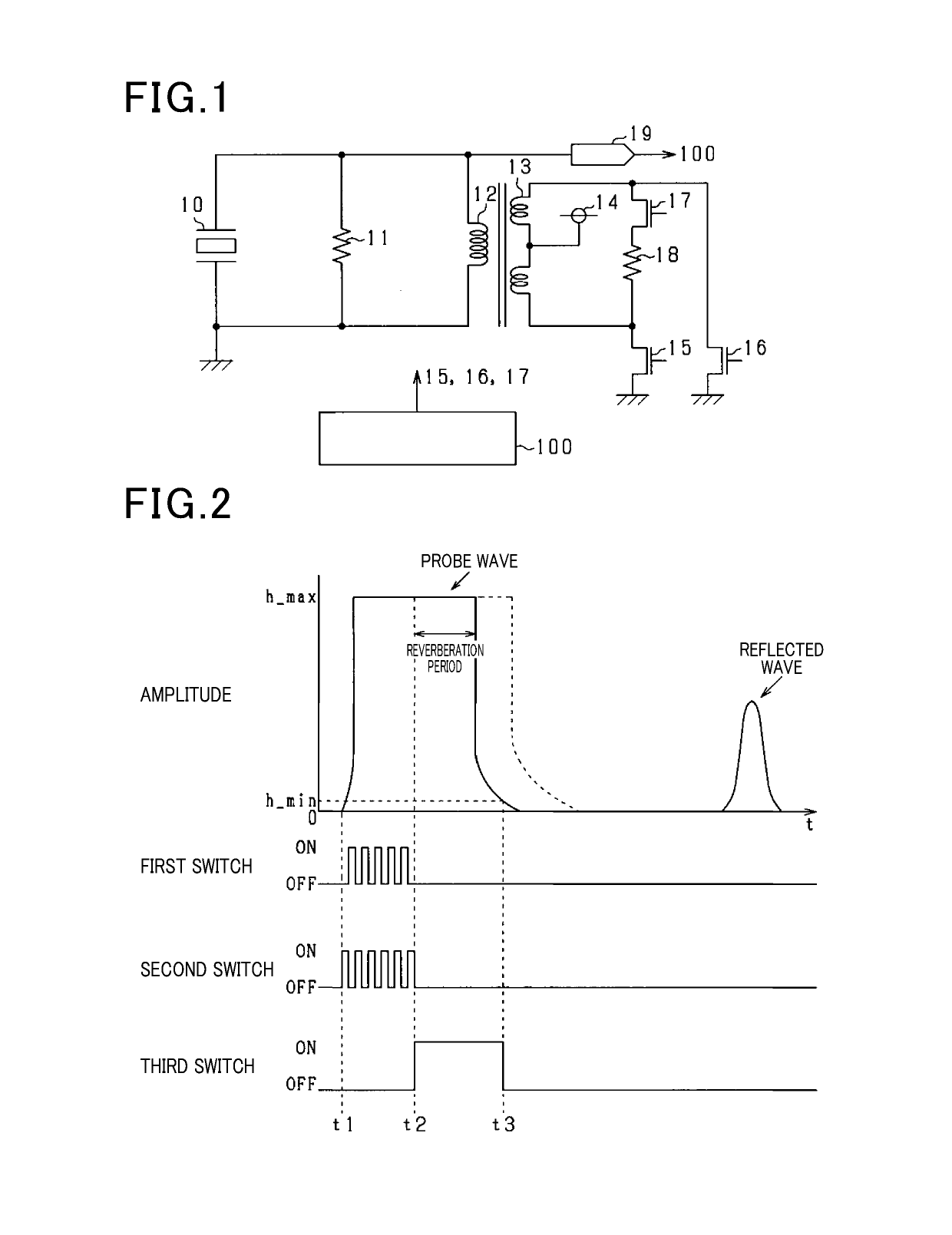
[0021]An object detection apparatus according to the present embodiment is an ultrasonic sensor and is installed in a mobile body such as a vehicle. The ultrasonic sensor transmits ultrasonic waves to the surroundings of the mobile body, receives reflected waves that are reflected from an object in the surroundings of the mobile body, and obtains the distance between the mobile body and the object by measuring the time interval between the transmission and the reception.

[0022]FIG. 1 is a circuit diagram of the ultrasonic sensor according to the present embodiment. With this ultrasonic sensor, ultrasonic waves are transmitted by applying voltage to a piezoelectric vibrator 10, and the energy of reflected waves received by the piezoelectric vibrator 10 is converted to voltage. A first resistor 11 and a first coil 12 are connected in parallel with the piezoelectric vibrator 10. The first coil 12 is magnetically coupled to the second coil 13, thereby forming a transformer. The second co...

second embodiment

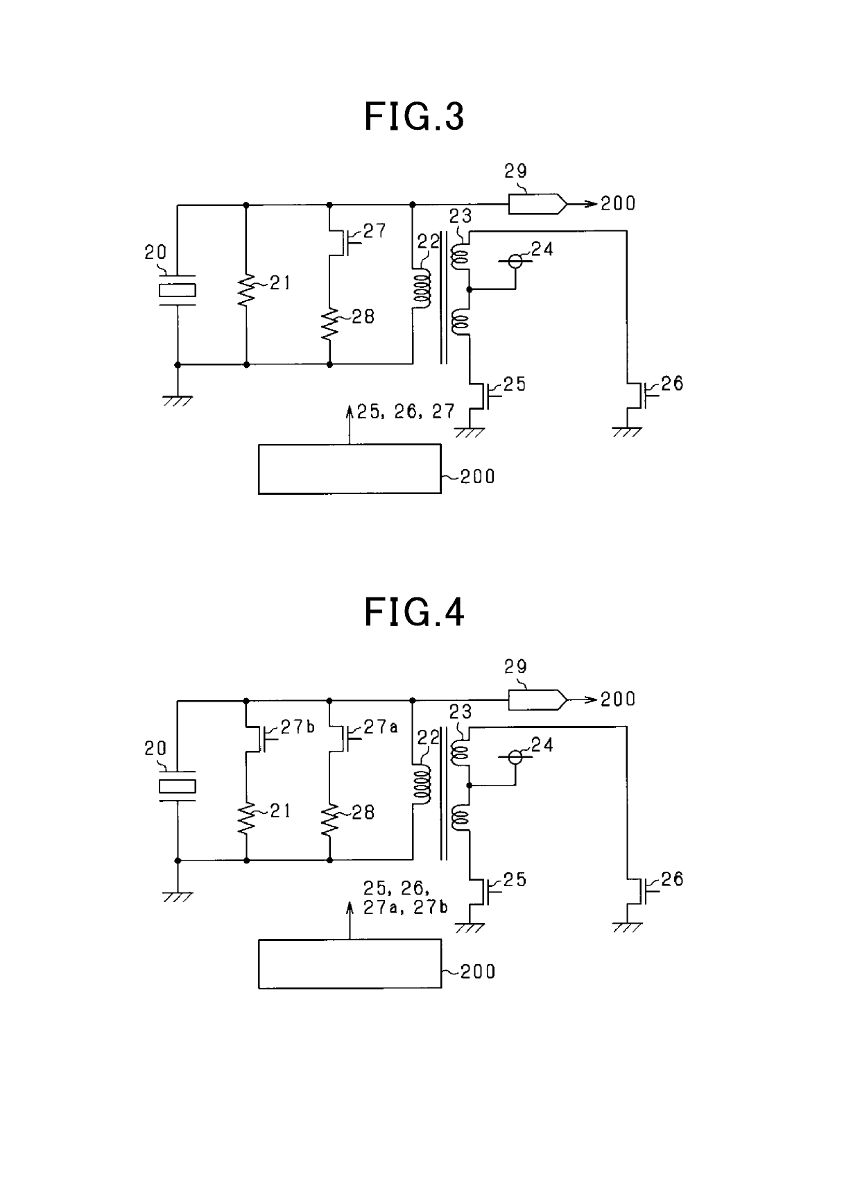
[0037]The ultrasonic sensor of the present embodiment differs from the ultrasonic sensor according to the first embodiment in part of the circuit configuration. FIG. 3 is a circuit diagram of the ultrasonic sensor according to the present embodiment.

[0038]A first resistor 21 and a first coil 22 are connected in parallel with a piezoelectric vibrator 20. The first coil 22 is magnetically coupled to a second coil 23, thereby forming a transformer. The second coil 23 includes a center tap, to which a power source 24 is connected. A first end of the second coil 23 is connected to the ground via a first switch 25 and a second end of the second coil 23 is connected to the ground via a second switch 26.

[0039]Furthermore, a series-connected body consisting of a third switch 27 and a second resistor 28 is connected in parallel with the piezoelectric vibrator 20. That is, a resistor section is formed by the first resistor 21, the second resistor 28, and the third switch 27. Hence, when the th...

third embodiment

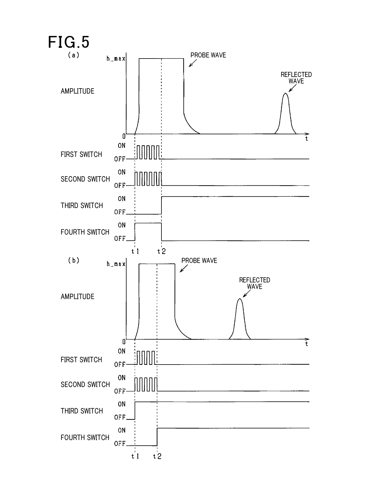
[0041]With this embodiment, the circuit configuration is similar to that in the second embodiment, but the embodiment differs in part of the processing performed by the control section 200. With the present embodiment, there is a long-distance mode (first mode) in which the reverberation period is allowed to become long, and in which the detection performance for reflected waves that are reflected from distant objects is enhanced, and a short-distance mode (second mode) in which the reverberation period is shortened and in which reflected waves from nearby objects can also be detected. Each of the long-distance mode and the short-distance mode has a single control opportunity during a predetermined time interval that starts from the time of transmitting the probe waves. For example, after one control opportunity has ended, a judgment is made as to whether or not to switch over to the long-distance mode or the short-distance mode.

[0042]In the long-distance mode, the third switch 27 i...


PUM


Abstract

An object detection apparatus drives a piezoelectric vibrator to transmit an ultrasonic wave, and receives a reflected wave that is reflected from an object. The object detection apparatus includes the piezoelectric vibrator, a drive circuit that supplies drive power which drives the piezoelectric vibrator, and a resistor section that is connected in parallel with the piezoelectric vibrator and has a resistance value that is variable.

Description

CROSS-REFERENCE TO RELATED APPLICATIONS[0001]The present application is based on Japanese Patent Application No. 2016-055826 filed on Mar. 18, 2016, the description of which is incorporated herein by reference.TECHNICAL FIELD[0002]The present disclosure relates to an object detection apparatus that transmits probe waves and receives reflected waves that are reflected from objects.BACKGROUND ART[0003]With an object detection apparatus which transmits probe waves, receives reflected waves that are reflected from an object, and detects the distance to the object, reverberation is produced when the probe waves are transmitted. The energy of the reverberation is typically significantly greater than the energy of the reflected waves, so that even if the reflected waves are received during a period (reverberation period) in which the reverberation is produced, it is difficult to detect the reflected waves.[0004]An ultrasonic sensor is described in PTL 1, as a sensor which shortens the reve...

Claims


Application Information

Patent Timeline
IPC IPC(8): G01S7/521G01S15/04G01S15/931G01S15/93
CPCG01S7/521G01S15/04G01S15/93G01S7/524G01S7/526G01S15/931
Inventor MATSUURA, MITSUYASUHARADA, TAKETOAOYAMA, TETSUYAKOYAMA, YU
Owner DENSO CORP
Why Eureka
Eureka Blog
Learn More