
Combination Tool Attachment System

a tool and tool technology, applied in the field of hand tools and accessories, can solve the problems of unusable design, useless end of the wrench for its intended use, useless end for turning bolts, etc., and achieve the effects of reducing operating costs, increasing productivity, and ensuring safety

Inactive Publication Date: 2019-04-18
PURE SAFETY GRP INC
View PDF4 Cites 2 Cited by
  • Summary
  • Abstract
  • Description
  • Claims
  • Application Information

AI Technical Summary

Benefits of technology

The present invention is a combination tool connector system that improves safety, productivity, and reliability. It includes a connector that is attached to a hand tool and can move along its handle without interfering with the tool's working end. The connector can be used to connect to various safety or security straps. Additionally, the invention includes a body shaft with an adaptor channel and a ring connector that can interact with a carabiner, allowing for secure attachment of the tool to a lanyard fastener. The adaptor channel is designed to prevent interference with the tool's working end and the length of the ring connector is greater than the length of the tool's margin portions to ensure proper fitting.

Problems solved by technology

One limitation of currently-available tool attachment methods is that some methods rely on the tool having an unused or free end of the handle to which a rubber sleeve or ring may be attached.
This design is not useful, however, for two-ended tools with functional features on each end of the tool.
Attaching a ring by using a sleeve formed over either end of the combination wrench renders that end of the wrench useless for its intended use.
Similarly, connecting a ring through the box-end of a wrench renders that end useless for turning bolts because the ring is in the way of the bolt head.
One limitation of attachment assemblies that include a leader secured to the tool with heat shrink tubing is that this design has proven unreliable.
The assembly fails because the leader may be inadvertently pulled out from the heat shrink tubing.

Method used


Image

  • Combination Tool Attachment System
  • Combination Tool Attachment System
  • Combination Tool Attachment System

Examples


Embodiment Construction

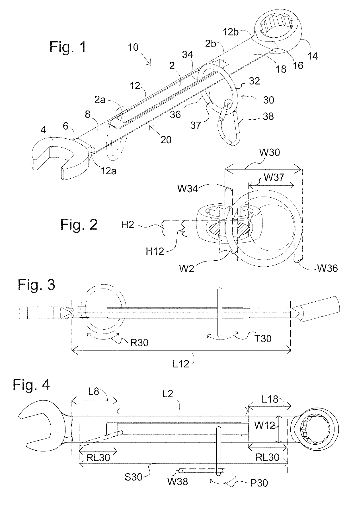
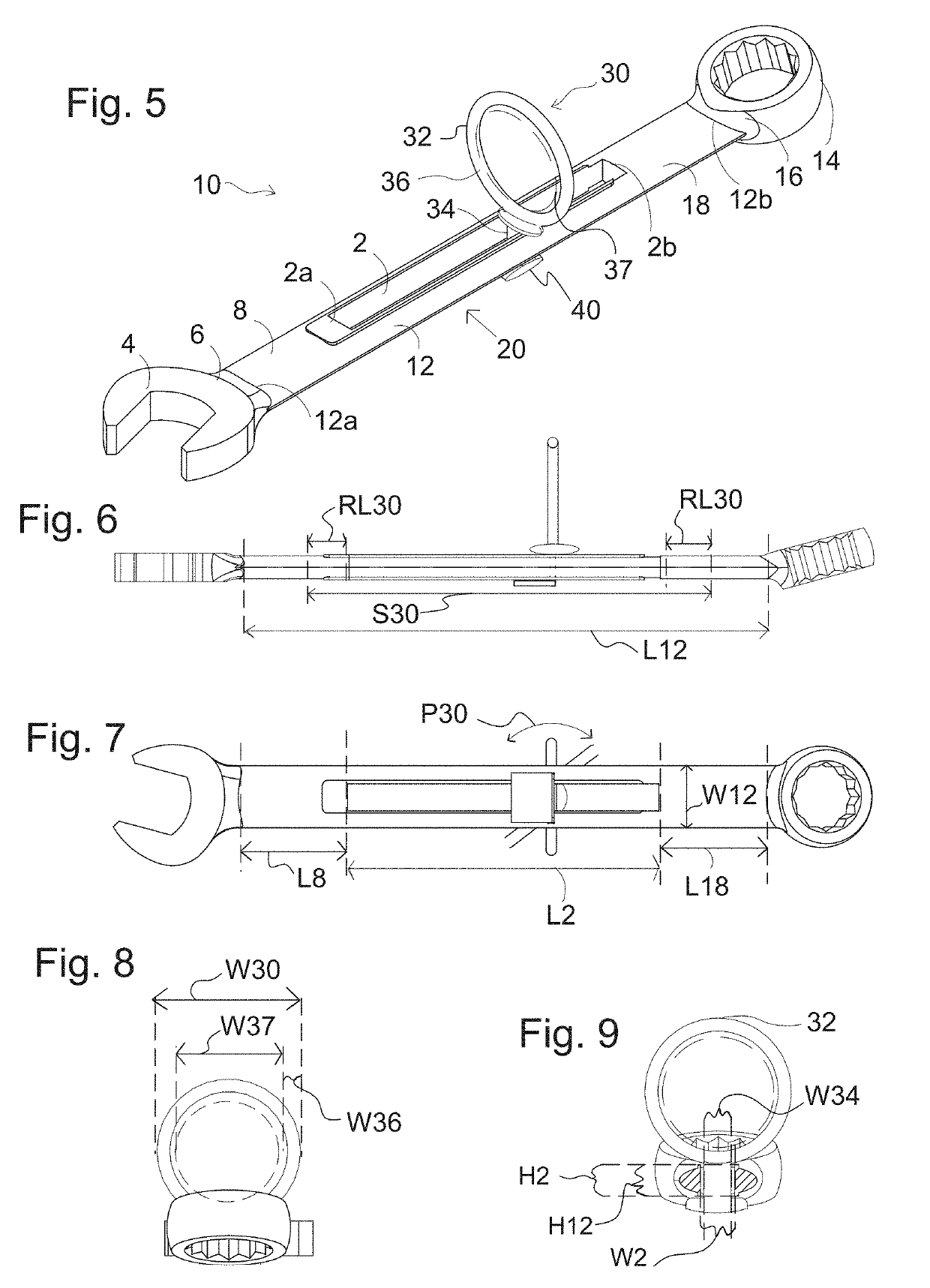
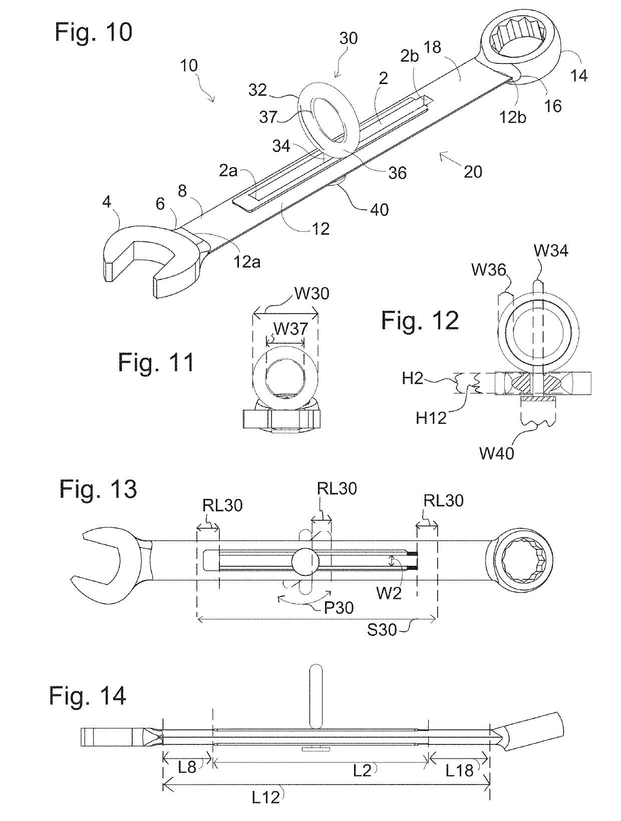
[0055]The preferred embodiments of the present invention are illustrated in FIGS. 1-43. Features which are universal to the present invention, regardless of embodiment, will now be discussed generally. Structural features are indicated via reference numbers, i.e., system ‘10’, tool ‘20’, etc. Various dimensions and directional movements of relevant features are referenced alphanumerically, i.e., ‘W’ for width (or diameter), “L” for length, ‘H’ for height, ‘S’ sliding direction, ‘R’ for rotational direction, ‘T’ for tilting direction, and ‘P’ for pivotal direction.

[0056]Combination Tool with Adaptor Channel

[0057]The present invention is a combination tool attachment system 10 having a combination tool 20 with at least one elongated adaptor channel 2 along a middle portion 12a of a body shaft 12 of the tool 20. A ring connector 30 is attached to the body shaft 12 of the combination tool 20 via the at least one adaptor channel 2.

[0058]Combination tools 20 are defined as those tools hav...


PUM


Abstract

A combination tool attachment system for combination hand tools and other dual working end tools, having a small body shaft, e.g., a combination wrench, or having a large body shaft, e.g., a combination crowbar. More specifically the present invention provides a combination tool attachment system which enables secure fastening of the combination tool to a lanyard fastener via a connector ring. The combination tool has margin portions along the body shaft to prevent the connector ring from interfering with either working end of the combination tool.

Description

BACKGROUND OF THE INVENTION1. Field of the Invention[0001]The present invention relates generally to hand tools and accessories. More particularly, the present invention relates to a combination tool attachment system for combination hand tools and other dual working end tools.2. Description of the Prior Art[0002]Hand tools are widely used in construction, maintenance, and industrial facilities operations. The user of a tool often stores tools in a bag, box, pouch, or tool belt when the tool is not being used. The user then selects the appropriate tool for a given task and returns the tool to its storage location after the task is complete. For tasks performed at elevated heights, dropping a tool can cause injury to individuals or damage to objects below the worker. The dropped tool also is a significant inconvenience for workers who must spend time to retrieve the dropped tool.[0003]Tool makers have partially addressed the problem of dropped tools by attaching a ring or grommet to ...

Claims


Application Information

Patent Timeline
Patent Type & Authority Applications(United States)
IPC IPC(8): B25G1/10B25B13/04B25B13/08B25B23/16B66F15/00B66F17/00
CPCB25G1/102B25B13/04B25B13/08B25B23/16B66F15/00B66F17/00F16B45/00B25H3/00A45F2005/006A45F2200/0575F16B45/002
Inventor MOREAU, DARRELL A.MOREAU, ANDRE W.
Owner PURE SAFETY GRP INC
Learn More