Ocean wave energy exploiting and storing device

Active Publication Date: 2019-04-18
NGUYEN DINH CHINH
View PDF22 Cites 2 Cited by
  • Summary
  • Abstract
  • Description
  • Claims
  • Application Information

AI Technical Summary

Benefits of technology

[0007]Since the accumulator is installed within the pillar, the capacity of the accumulator is enhanced and the weight of the second work platform affects the axle head of

Problems solved by technology

The weaknesses of current devices include incapacity of energy storage, low level of gene

Method used


Image

  • Ocean wave energy exploiting and storing device

Examples


Embodiment Construction

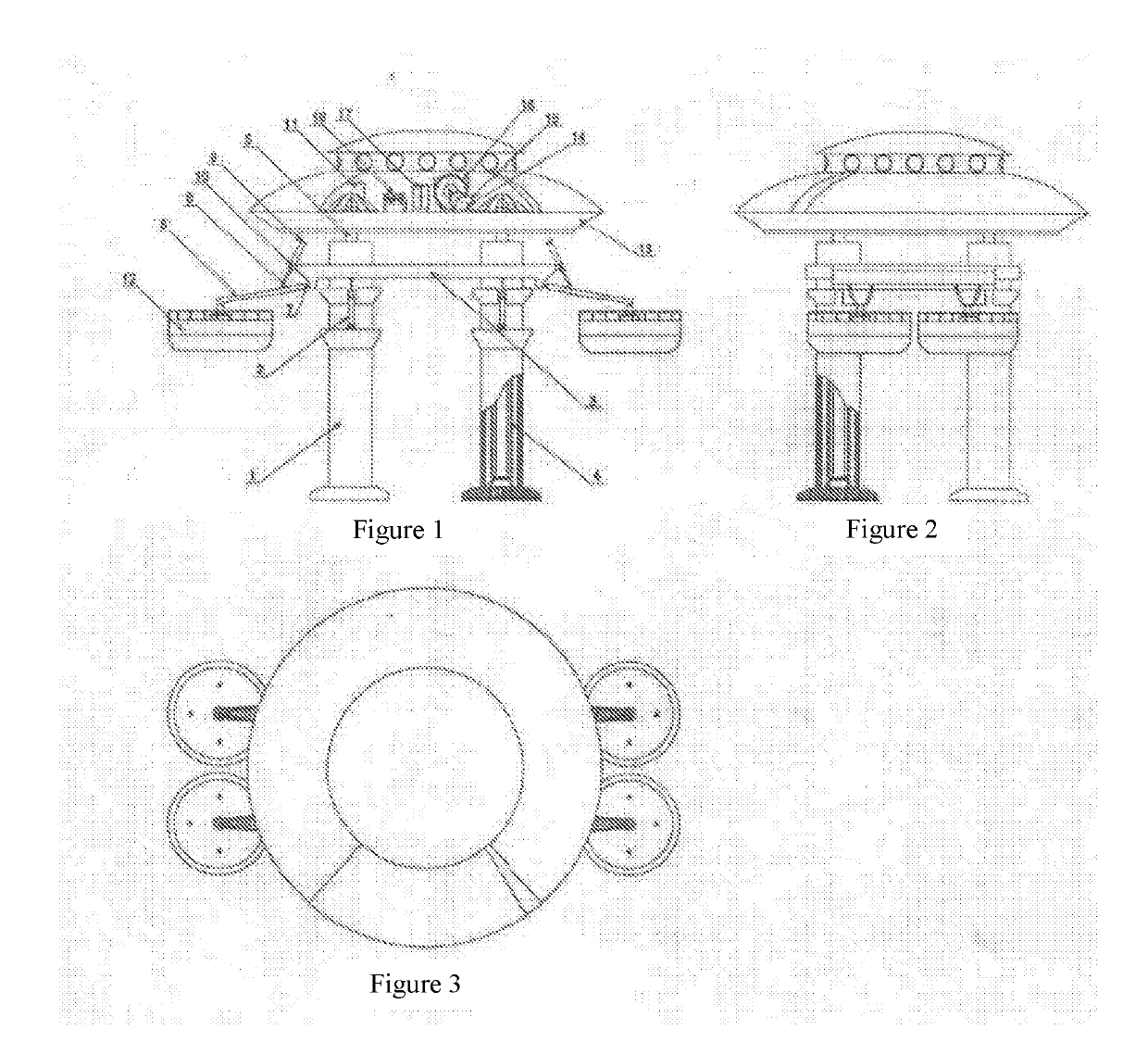
[0011]As illustrated in FIG. 1, the ocean wave energy exploiting and storing device includes: At least one hollow pillar (1) installed on the ocean bed with the head emerging out of the sea water. The outer surface of the pillar is made of salt resistant material with slots to install hydraulic cylinders (2) to lift the first platform (3) and a base to support the first platform (3). The pillar is also the cover for a weight-loaded type accumulator. This high volume accumulator (4) is installed inside the pillar. The center axle of the accumulator is higher than the pillar head to install the second platform. This second floor always weight on the axle head of the accumulator to press the oil for pressure. The pillar is not only used to support the work platforms but also the location to install the high volume accumulator.

[0012]The first platform (3) cover the pillar head above the sea level and can move up and down thanks to the operation of the hydraulic cylinder (2). The cylinde...


PUM


Abstract

The present invention related to the ocean wave energy exploiting and storing device for electricity generation. The device consists of one hollow pillar (1), the pillar has a base to install the platform (3) and a slot for the hydraulic cylinder (2). The weight-loaded type accumulator (4) is installed within the pillar; two work platform (3) and (13) installed separately which work independently on each other. The first platform (3) covers the head of the pillar above the sea level and can move up and down. The level arm (6) is equipped with the hydraulic cylinder (9 via a swivel joint (10). There is a buoy (12) installed on the other end of the level arm. The second platform (13) is placed on the head of the pressing axle (5) above the first one (3).

Description

FIELD OF THE INVENTION[0001]The present invention relates to the ocean wave energy exploiting and storing device.BACKGROUND OF THE INVENTION[0002]It is now possible to exploit energy from ocean waves for electricity generation by floating buoy which is a device with buoy-attached lever arm and there are hydraulic cylinders attached to lever arm for oil pumping or floating buoy is attached to the axle head of hydraulic cylinders. Ocean waves will lift the buoy up and down to pump oil to an accumulator pressed by pressure generating gas to provide energy directly for the turbine or the hydraulic motor. The hydraulic motor provides energy for the turbine to generate electricity by rotation, or for the hydraulic cylinders for its pulling and pushing movement upon the equipment clusters which are equipped with permanent magnets to generate electricity through oscillation.[0003]The weaknesses of current devices include incapacity of energy storage, low level of generated pressure and low ...

Claims


Application Information

Patent Timeline
IPC IPC(8): F03B13/18
CPCF03B13/1845F03B13/1815F05B2240/40F05B2240/91F05B2240/915F05B2240/95F05B2260/406Y02E10/30
Inventor NGUYEN, DINH CHINH
Owner NGUYEN DINH CHINH
Why Eureka
Try Eureka