Self-expandable filler for mitigating paravalvular leak

a filler and paravalvular technology, applied in the field of heart valve replacement, can solve problems such as paravalvular leakage and pv leakag

Active Publication Date: 2019-04-25
ST JUDE MEDICAL CARDILOGY DIV INC
View PDF7 Cites 22 Cited by
  • Summary
  • Abstract
  • Description
  • Claims
  • Application Information

AI Technical Summary

Problems solved by technology

After implantation, imperfect sealing between the prosthetic valve and the native tissue at the site of implantation may cause complications such as paravalvular leakage (“PV leak”) in which retrograde blood flows through one or more gaps formed between the structure of the implanted valve and cardiac tissue as a result of the imperfect sealing.

Method used


Image

  • Self-expandable filler for mitigating paravalvular leak
  • Self-expandable filler for mitigating paravalvular leak
  • Self-expandable filler for mitigating paravalvular leak

Examples


Embodiment Construction

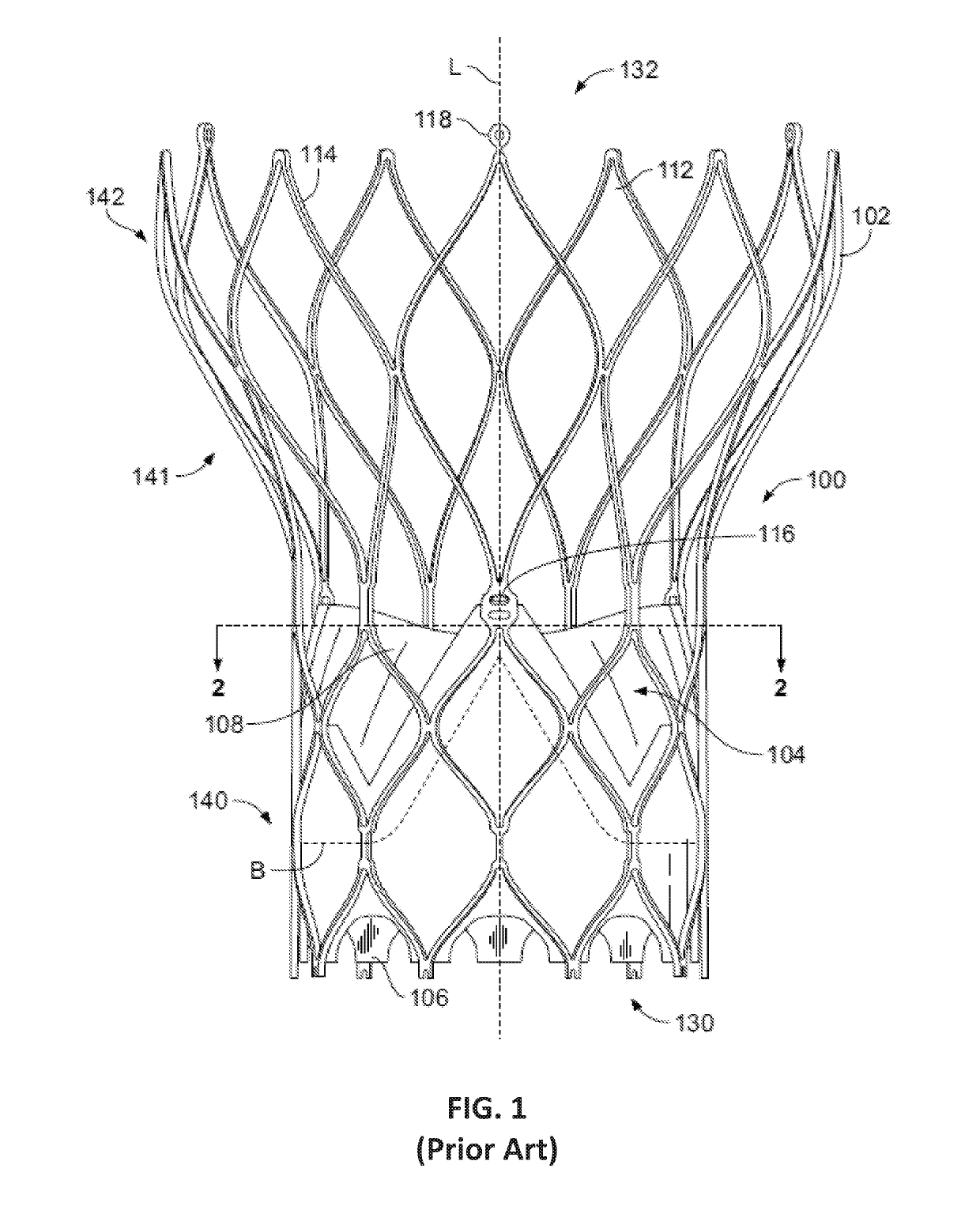
[0018]As used herein in connection with a prosthetic heart valve, the term “inflow end” refers to the end of the heart valve through which blood enters when the valve is functioning as intended, and the term “outflow end” refers to the end of the heart valve through which blood exits when the valve is functioning as intended. As used herein, the term “proximal” refers to the inflow end of a prosthetic heart valve or to elements of a prosthetic heart valve that are relatively close to the inflow end, and the term “distal” refers to the outflow end of a prosthetic heart valve or to elements of a prosthetic heart valve that are relatively close to the outflow end. As used herein, the terms “generally,”“substantially,” and “about” are intended to mean that slight deviations from absolute are included within the scope of the term so modified. Like numbers refer to similar or identical elements throughout. When used herein in the context of a prosthetic heart valve, or a component thereof...


PUM


Abstract

A prosthetic heart valve includes a collapsible stent and a valve assembly disposed within the stent. A first cuff is disposed adjacent the stent. A filler is annularly disposed about the stent radially outward of the first cuff and radially outward of the stent. The filler has a first circumferential layer with a first inner wall, a first outer wall, and a plurality of first ribs connecting the first inner wall to the first outer wall. The filler has an expanded condition in which the first inner wall is spaced a first distance from the first outer wall in a radial direction transverse to the longitudinal direction of the stent, and a collapsed condition in which the first inner wall is spaced a second distance from the first outer wall in the radial direction, the first distance being greater than the second distance.

Description

CROSS-REFERENCE TO RELATED APPLICATIONS[0001]This application claims the benefit of the filing date of U.S. Provisional Patent Application No. 62 / 576,204, filed Oct. 24, 2017, the disclosure of which is hereby incorporated by reference herein.BACKGROUND OF THE DISCLOSURE[0002]The present disclosure relates to heart valve replacement and, in particular, to collapsible prosthetic heart valves. More particularly, the present disclosure relates to collapsible prosthetic transcatheter heart valves that minimize or reduce paravalvular leaks.[0003]Prosthetic heart valves that are collapsible to a relatively small circumferential size can be delivered into a patient less invasively than valves that are not collapsible. For example, a collapsible valve may be delivered into a patient via a tube-like delivery apparatus such as a catheter, a trocar, a laparoscopic instrument, or the like. This collapsibility can avoid the need for a more invasive procedure such as full open-chest, open-heart s...

Claims


Application Information

Patent Timeline
Patent Type & Authority Applications(United States)
IPC IPC(8): A61F2/24
CPCA61F2/246A61F2/2418A61F2250/0069A61F2/2445A61F2/90A61F2210/0076A61F2250/0039A61F2/24
Inventor LI, XUE MEIMEYER, MICHAEL P.
Owner ST JUDE MEDICAL CARDILOGY DIV INC
Why Eureka
Try Eureka