
Unicondylar tibia implants

a technology of tibia implants and unicondylar, which is applied in the field of unicondylar knee arthroplasty implants, can solve the problems of patient complications, adversely affecting the performance reliability, performance and/or wear of the implant device,

Active Publication Date: 2019-04-25
SMITH & NEPHEW INC
View PDF2 Cites 0 Cited by
  • Summary
  • Abstract
  • Description
  • Claims
  • Application Information

AI Technical Summary

Benefits of technology

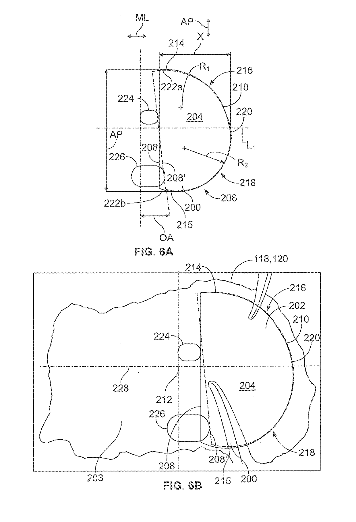
The present application provides unique implant devices for implantation on a tibia that can include an outer edge with specific dimensions and shapes. The outer edge can have a first edge, a second edge, an anterior edge, and a posterior edge, with at least a portion of each edge separated by a specific distance. The implant device can also include a lateral curve, a posterior curve, and an anterior curve, which can have different radii of curvature and extend along the second edge. The various shapes and dimensions of the implant device can provide improved outcomes and reduced complications during surgery.

Problems solved by technology

Such devices however can suffer from a number of issues, including issues relating to reliability, performance, and / or wear of the implant device.
For example, implantation on the lateral compartment of a tibia implant device that is designed for use on the medial compartment of the opposite hand can adversely impact the performance of the implant device, as there can be a lack of anatomic conformance to the lateral geometry of the resected tibia.
Further, poor tibial fit on both the medial and lateral tibial plateaus can lead to patient complications.
Additionally, compromises are often made as to the size of the implant device when the implant device is used in the opposite compartment.
Moreover, such an approach may not fully satisfy the anatomic requirements of the off design secondary application.
Such compromises and / or the lack of anatomic conformance can provide less than ideal implanted conditions in each application.
Yet, in addition to being costly, such an approach further exposes the patient to additional medical scanning.

Method used


Image

  • Unicondylar tibia implants
  • Unicondylar tibia implants
  • Unicondylar tibia implants

Examples


Embodiment Construction

[0047]Certain terminology is used in the foregoing description for convenience and is not intended to be limiting. Words such as “upper,”“lower,”“top,”“bottom,”“first,” and “second” designate directions in the drawings to which reference is made. This terminology includes the words specifically noted above, derivatives thereof, and words of similar import. Additionally, the words “a” and “one” are defined as including one or more of the referenced item unless specifically noted. The phrase “at least one of” followed by a list of two or more items, such as “A, B or C,” means any individual one of A, B or C, as well as any combination thereof. As used herein, the terms “about” and “substantially” may be applied to modify any quantitative representation that could permissibly vary without resulting in a change in the basic function to which it is related.

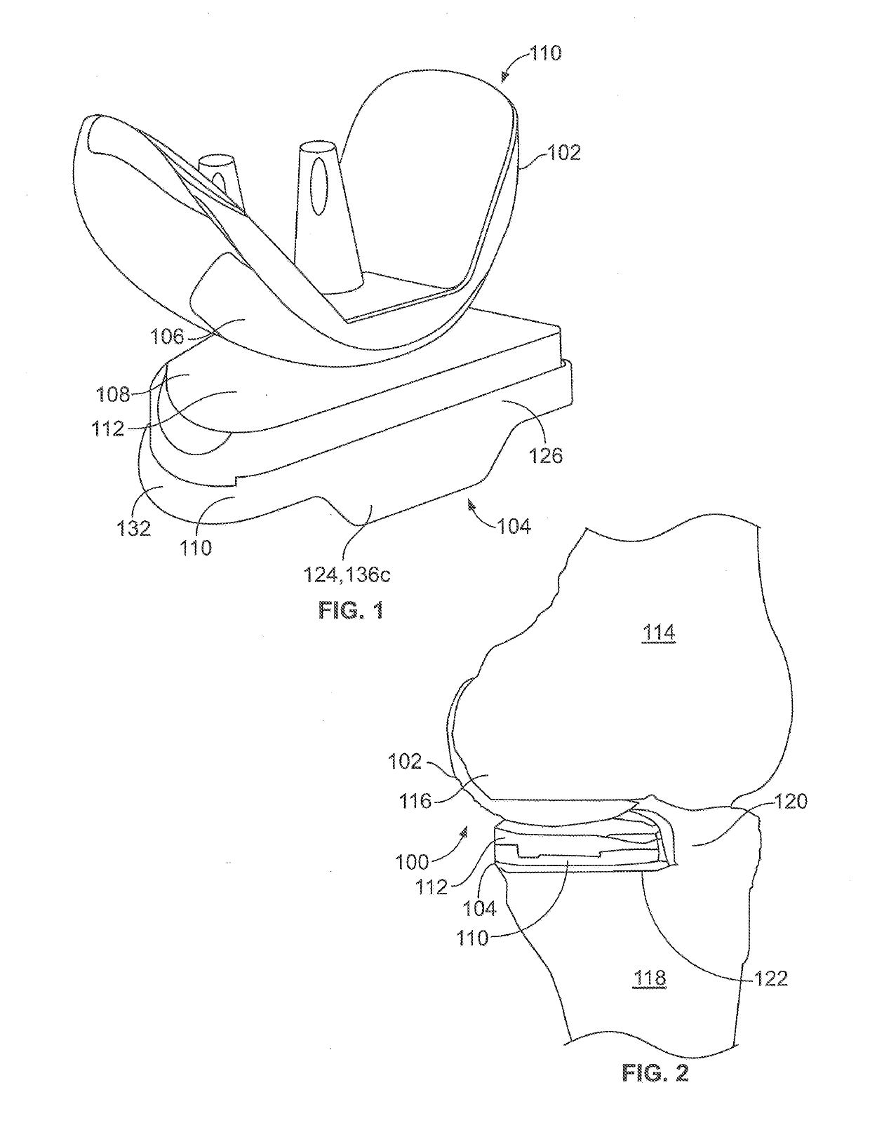
[0048]FIG. 1 illustrates a side perspective view of an exemplary implant 100 that can be utilized for unicompartmental knee replaceme...


PUM


Abstract

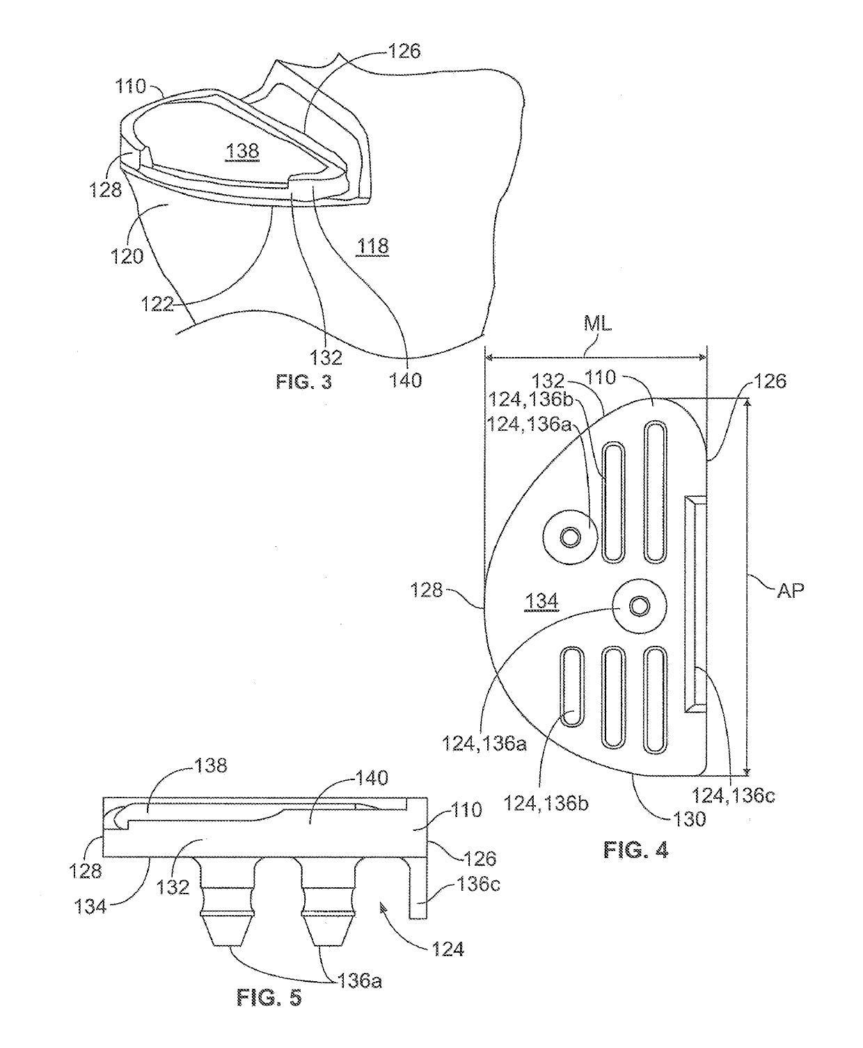
Unicondylar tibia implant devices having a bone-facing, distal side that can be detailed with cement fixation features and may include any of or a plurality of grooves, pegs, fins, rails, cavities, and / or coating whereby the geometry of the implant device improves implant-to-cement or cement-to-bone fixation characteristics exceeding that of a traditional flat surface. The implant device may also include a proximal side facing away from the bone-facing, distal side and having a geometry that provides either articulation with (cartilage and meniscal substituting) or receipt of a secondary device coupleable to the implant device on the distal side of the secondary device that features an away-from-bone facing articulating feature. Additionally, the geometry of the implant device in anterior-posterior and medial-lateral directions, among other directions, provides a variety of improvements relative to currently available devices.

Description

BACKGROUND[0001]Embodiments of the present application generally relate to implant devices for unicondylar knee arthroplasty. More particularly, but not exclusively, embodiments of the present application relate to anatomically shaped tibial implant devices for unicondylar knee arthroplasty.[0002]Partial (unicondylar) knee arthroplasty, also referred to as unicompartmental knee replacement or partial knee replacement, is a procedure in which one of either the medial or lateral compartments of the distal femur and / or the proximal tibia can be replaced with an implant device. Typically, implant devices used for partial knee arthroplasty are designed to at least attempt to anatomically fit the proximal tibia anatomy of the patient. Moreover, at least certain types of implant devices used for partial knee arthroplasty have been designed to be interchangeable between compartment / hand, such that the opposite hand / compartment can be used as a secondary placement recommendation. For example...

Claims


Application Information

Patent Timeline
Patent Type & Authority Applications(United States)
IPC IPC(8): A61F2/38
CPCA61F2/389A61F2002/30131A61F2002/30187A61F2002/30708A61F2002/30892A61F2002/30884A61F2002/3895A61F2002/30878
Inventor CYKO, CHRISTOPHER RAYJORDAN, JASON SEAN
Owner SMITH & NEPHEW INC
Learn More