
Vehicle control apparatus

a technology of vehicle control and control apparatus, which is applied in the direction of braking system, transportation and packaging, road transportation, etc., can solve the problems of discontinuous deceleration of the vehicle, insufficient braking force, and operation delay in actual transition, so as to reduce or prevent sudden change of vehicle deceleration, reduce or prevent discontinuity of deceleration, and improve drivability

Active Publication Date: 2019-04-25
DENSO CORP
View PDF0 Cites 5 Cited by
  • Summary
  • Abstract
  • Description
  • Claims
  • Application Information

AI Technical Summary

Benefits of technology

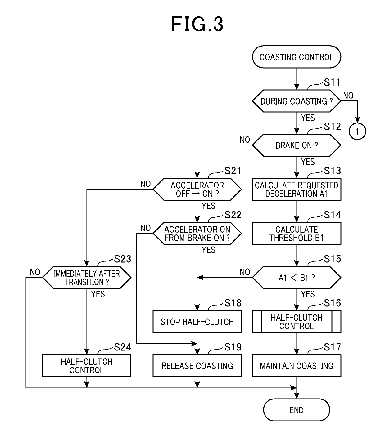
The present invention aims to provide a vehicle control system that can smoothly transition between coasting and non-coasting modes while maintaining appropriate deceleration control. By performing a half-clutch control at the beginning or before cancellation of coasting, the invention prevents sudden changes in vehicle deceleration due to changes in braking force caused by engine rotation. This results in a seamless switch between coasting and non-coasting modes, improving overall driving experience.

Problems solved by technology

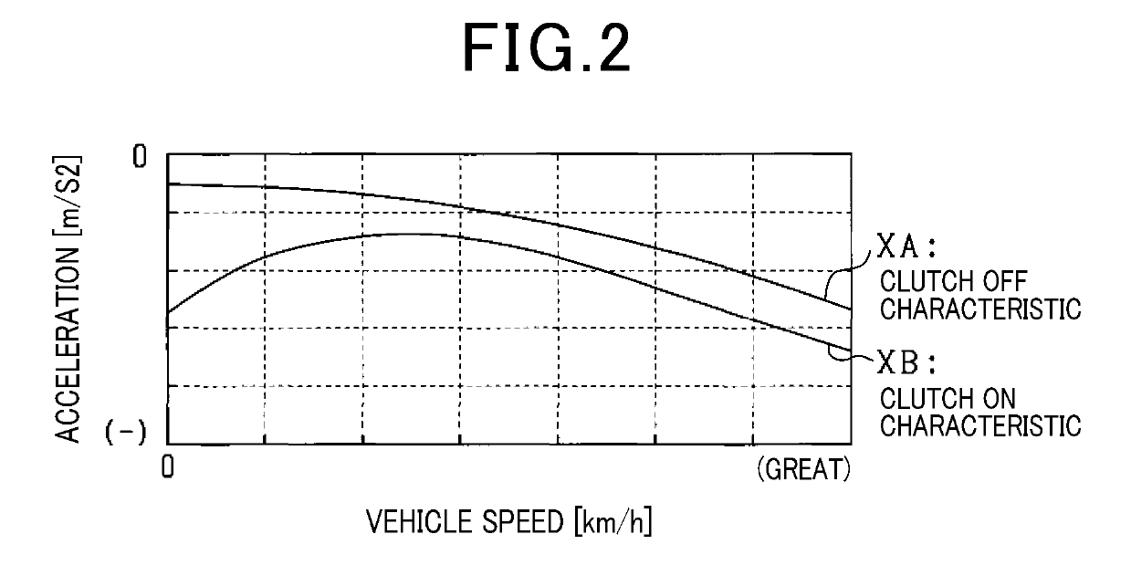
When switching between coasting and non-coasting is performed, a power transmission path connected to the engine is intermittent by the clutch device, and thus deceleration of the vehicle may be discontinuous before and after the switching.
However, when the clutch device is switched to an engaged state or a disengaged state, an operation delay occurs in an actual transition to the engaged state or the disengaged state in response to a command to the clutch device.
According to the technique of Patent Literature 1, therefore, a braking force may not be appropriately added by the friction brake, and this may impair continuity of the deceleration.
For example, when the clutch device is activated according to hydraulic pressure, a delay may occur in change in the hydraulic pressure in response to a command, and this may damage continuity of the deceleration.

Method used


Image

  • Vehicle control apparatus
  • Vehicle control apparatus
  • Vehicle control apparatus

Examples


first embodiment

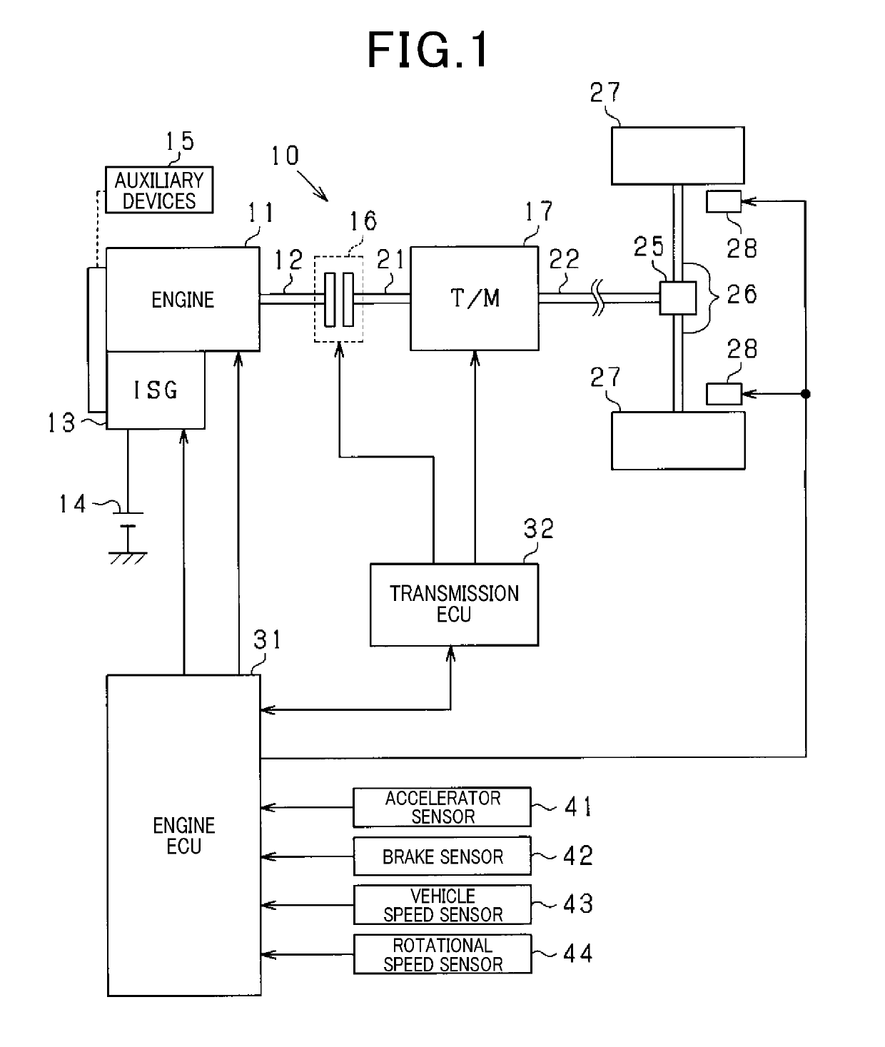
[0028]In a vehicle 10 illustrated in FIG. 1, an engine 11 is a multi-cylinder internal combustion engine which is driven by combustion of fuel such as gasoline, diesel oil, or the like. As well known, the engine 11 includes a fuel injector, an ignition device, and the like as appropriate. An ISG 13 (Integrated Starter Generator) as an electric motor is integrally mounted with the engine 11, and a rotating shaft of the ISG 13 is drive-coupled to an engine output shaft 12 with a belt or the like. In this case, the rotating shaft of the ISG 13 is rotated by rotation of the engine output shaft 12, while the engine output shaft 12 is rotated by rotation of the rotating shaft of the ISG 13. Specifically, the ISG 13 has a power generation function of generating electric power (regenerative power generation) by the rotation of the engine output shaft 12 and a power running function of providing a rotational force to the engine output shaft 12. When the engine 11 is started, the engine 11 pe...

second embodiment

[0105]According to the present embodiment, in a case where the half-clutch control has been performed immediately before coasting is cancelled and coasting is cancelled by operating the accelerator ON in coasting state, an acceleration assist with the driving force of the ISG 13 is provided based on a remaining engagement degree which remains in the clutch device 16 after the half-clutch control ends when the accelerator is ON.

[0106]FIG. 13 is a flow chart showing a procedure for coasting control, and the present process is a process partially modified from the process in FIG. 4 mentioned above. For convenience, in FIG. 13, the same steps as those in FIG. 4 are given the same step numbers.

[0107]In FIG. 13, when an affirmative determination (YES) is made at step S38, i.e., when, for example, conditions that the vehicle 10 is in the normal traveling state, coasting has been cancelled immediately beforehand, and an acceleration request has been made are all satisfied, the process proce...

third embodiment

[0112]The acceleration assist process at step S39 in FIG. 4 may be implemented as shown in FIG. 15. Specifically, when coasting has been cancelled immediately beforehand and an acceleration request has been made, the acceleration assist process in FIG. 15 is performed.

[0113]In FIG. 15, at step S61, it is determined whether the engine 11 is in the stop state, i.e., a state in which combustion stops. When the engine 11 is in the stop state, the process proceeds to step S62, and the when the engine 11 is in the operating state, the process proceeds to step S65.

[0114]At step S62, it is determined whether the engine rotational speed when the accelerator is ON is higher than a predetermined value K1. The predetermined value K1 is a threshold for determining whether the engine 11 which is in the stop state during coasting is in a rotation state in which the engine 11 is restartable by combustion of fuel, and, for example, K1=300 rpm. When the engine rotational speed is lower than the prede...


PUM


Abstract

A vehicle control apparatus is applied to a vehicle including an engine as traveling drive source and a clutch device in a power transmission path connected to an output shaft of the engine. The vehicle control apparatus causes the vehicle to be in a coasting state by reducing power transmitted in the path by clutch device operation upon satisfaction of a predetermined implementation condition, and cancels coasting state by clutch device operation upon satisfaction of a predetermined coasting cancellation condition including at least an accelerator condition during coasting. The vehicle control apparatus includes a travel determination section determining coasting state of the vehicle, and a clutch control section performing half-clutch control during coasting at least at one of at the beginning of coasting and immediately before coasting is cancelled, the half-clutch control setting a degree of clutch device engagement to an intermediate degree.

Description

CROSS-REFERENCE TO RELATED APPLICATIONS[0001]This application is based on Japanese Patent Application No. 2016-082728 filed on Apr. 18, 2016, the contents of which are incorporated herein by reference.TECHNICAL FIELD[0002]The present disclosure relates to a vehicle control apparatus.BACKGROUND ART[0003]In recent years, for improving fuel economy and the like, a technique has been applied to practical use in which, when an accelerator is turned OFF while a vehicle is traveling, the vehicle is caused to be in a coasting state by disengaging a clutch device provided between an engine and a transmission. For example, according to a technique described in Patent Literature 1, based on an amount of accelerator operation and an amount of brake operation performed by a driver, a requested acceleration / deceleration requested by the driver is calculated, and a first acceleration / deceleration of a vehicle in a non-coasting state and a second acceleration / deceleration of the vehicle in a coasti...

Claims


Application Information

Patent Timeline
Patent Type & Authority Applications(United States)
IPC IPC(8): B60W30/18B60W10/02B60K6/387B60K6/36B60K6/48B60W10/18B60W20/00B60W10/08
CPCB60W30/18072B60W10/02B60K6/387B60K6/36B60K6/48B60W10/18B60W20/00B60W10/08B60W2710/021B60W2540/10B60W2540/12B60W2710/18B60W2510/0638B60W2710/08B60Y2200/92B60Y2300/192B60W2510/0291B60T8/00B60W10/06B60W10/10F16D48/02Y02T10/62Y02T10/60B60W30/18063B60W30/18027
Inventor AKITA, TOSHIKAZUOSE, TOMOHISAMAEDA, SHIGERU
Owner DENSO CORP
Learn More