Active noise reduction device and active noise reduction method

a noise reduction device and noise reduction technology, applied in the direction of instruments, vehicle components, musical instruments, etc., can solve the problems of slow convergence rate, unusual noise generation, noticeable periodicity of noise, etc., and achieve the effect of stably reducing all harmonic components

Active Publication Date: 2019-05-02
PANASONIC INTELLECTUAL PROPERTY MANAGEMENT CO LTD
View PDF6 Cites 6 Cited by
  • Summary
  • Abstract
  • Description
  • Claims
  • Application Information

AI Technical Summary

Benefits of technology

[0013]According to the present invention, step size parameters suitable for each harmonic component of the control target sound are set, and filter coefficients are calculated using the respective set step size parameters. This configuration ensures adaptability per each harmonic component even in the case of a sudden change in engine rotation rate, such as during acceleration or deceleration. From this, the effect of stably reducing all harmonic components (especially high-order frequency components) of a control target sound arising from engine vibration is achieved.

Problems solved by technology

These devices reduce engine booming noise generated in a cabin of a traveling vehicle by letting the noise and a control sound with opposite phases and the same amplitude interfere with each other.
This noise shows noticeable periodicity in synchronization with a rotation rate of the engine.
If step size parameter g gets small, the algorithm improves in accuracy but slows in convergence rate.
In the case of a sudden change in engine rotation rate, the speed at updating filter coefficient W(n) may be inadequate to adapt to the sudden change and filter coefficient W(n) may diverge in the active noise reduction device described above, resulting in the generation of an unusual noise.

Method used


Image

  • Active noise reduction device and active noise reduction method
  • Active noise reduction device and active noise reduction method

Examples


Embodiment Construction

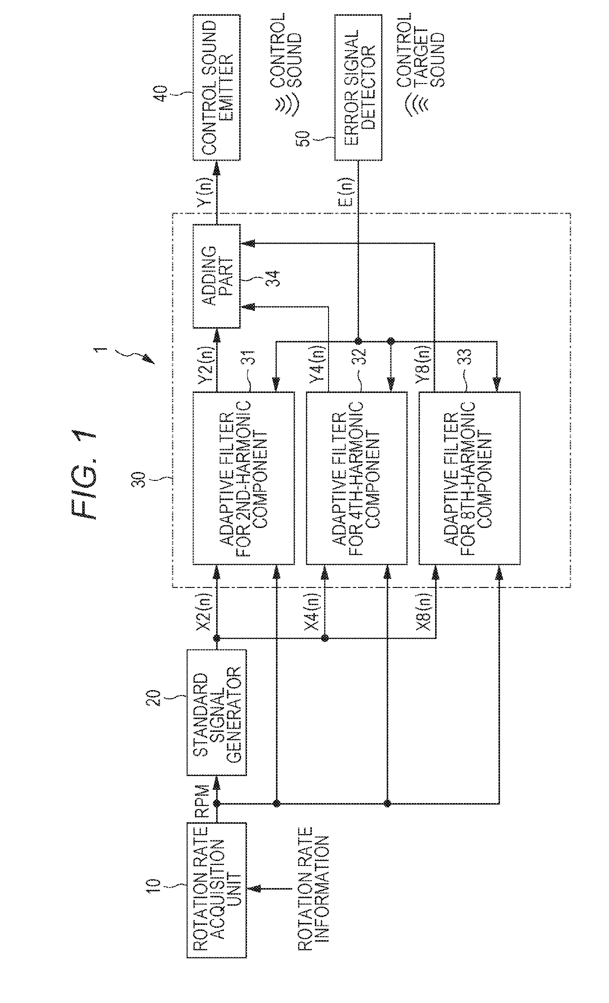
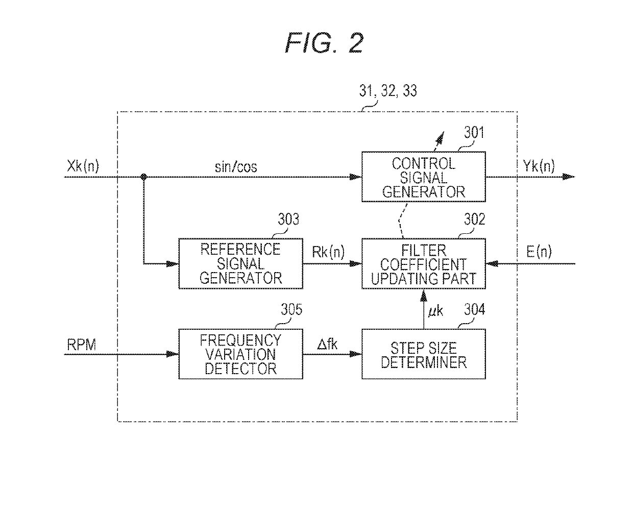
[0016]Before an exemplary embodiment of the present invention is described, problems in a conventional technique will be briefly described. In PTL 1, step size parameter p changes in line with a variation in the engine rotation rate, i.e. a fundamental frequency. Thus, adaptability to high-order frequency components (harmonic components) may decrease in the case of a sudden change in the engine rotation rate, such as during acceleration or deceleration. For example, a description will be given of a situation in which a threshold range of variation in fundamental frequency f0 is set to 1 Hz. This means that when a range of variation in the second-order component forming a fundamental wave reaches 2 Hz or greater, step size parameter p for the frequency component changes. In this case, until a range of variation in the fourth-order component reaches 4 Hz or greater, or until a range of variation in the eighth-order component reaches 8 Hz or greater, step size parameter p for the compo...


PUM


Abstract

An active noise reduction device includes a standard signal generator, adaptive filters, a control sound emitter, and an error signal detector. The standard signal generator generates a standard signal including harmonics of a fundamental frequency correlated with the control target sound. The adaptive filters each generates corresponding one of harmonic components of a control signal based on the standard signal. The adaptive filters each is for corresponding one of the harmonics. The control sound emitter emits a control sound based on the control signal. The error signal detector collects residual noise left over after interference between the control target sound and the control sound, and detects an error signal based on the residual noise. Each of the adaptive filters includes a step size determiner. The step size determiner sets the step size parameter based on a frequency variation in the corresponding one of the harmonic components of the standard signal.

Description

TECHNICAL FIELD[0001]The present invention relates to an active noise reduction device and an active noise reduction method that are used to actively reduce engine booming noise generated in a vehicle cabin along with engine vibration.BACKGROUND ART[0002]In recent years, active noise reduction devices for reducing engine booming noise have been put to practical use. These devices reduce engine booming noise generated in a cabin of a traveling vehicle by letting the noise and a control sound with opposite phases and the same amplitude interfere with each other. Engine booming noise is acoustic radiation generated by the resonance of a cabin of a vehicle, i.e. a closed space, under certain conditions in response to vibration transmitted from an engine through a body of the vehicle. This noise shows noticeable periodicity in synchronization with a rotation rate of the engine.[0003]An active noise reduction device includes an adaptive filter that allows a transfer function in an engine ...

Claims


Application Information

Patent Timeline
Patent Type & Authority Applications(United States)
IPC IPC(8): B60R11/02G10K11/178B60R13/08
CPCB60R11/0264G10K11/178B60R13/0838G10K2210/1282G10K11/17823G10K11/17854G10K11/17883
Inventor TAO, MASAFUMIYAMANASHI, TOMOFUMI
Owner PANASONIC INTELLECTUAL PROPERTY MANAGEMENT CO LTD
Why Eureka
Try Eureka