Robot control device

a robot control and robot technology, applied in the field of robot control devices, can solve problems such as reducing work efficiency, and achieve the effect of reducing collision possibility and high work efficiency

Active Publication Date: 2019-05-09
MITSUBISHI ELECTRIC CORP
View PDF0 Cites 2 Cited by
  • Summary
  • Abstract
  • Description
  • Claims
  • Application Information

AI Technical Summary

Benefits of technology

[0008]The present invention has the advantage of obtaining the robot control device that reduces possibility of collision between the worker and the robot while maintaining high work efficiency when the worker and the robot work while sharing the work space.

Problems solved by technology

However, stopping the operation, for collision prevention, whenever the robot and the worker come close to each other decreases work efficiency.

Method used


Image

  • Robot control device
  • Robot control device
  • Robot control device

Examples


first embodiment

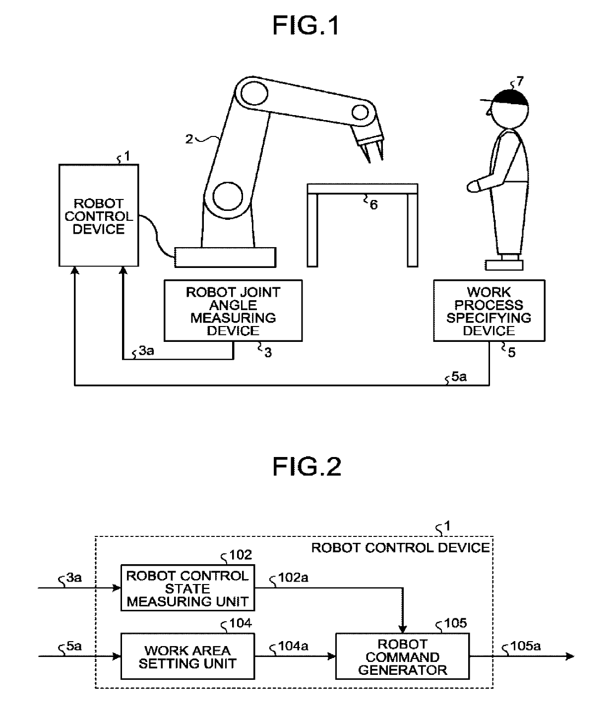
[0026]FIG. 1 schematically illustrates a robot system including a robot control device 1 according to the first embodiment of the present invention, and an example of a worksite to which the robot system is applied. The robot control device 1 illustrated in FIG. 1 is connected to a robot 2 and outputs a motion command to the robot 2 on the basis of a robot joint angle signal 3a from a robot joint angle measuring device 3 and a work process specifying signal 5a from a work process specifying device 5. In the worksite illustrated in FIG. 1, a workbench 6 is disposed, and a worker 7 is present. The robot 2 operates while sharing a work space with the worker 7.

[0027]FIG. 2 is a block diagram illustrating an example configuration of the robot control device 1 illustrated in FIG. 1. The robot control device 1 illustrated in FIG. 2 includes a robot control state measuring unit 102 that measures robot control state information 102a indicative of a robot position and a robot posture. The rob...

second embodiment

[0045]In the present embodiment, a description is provided of a robot command generator that operates in a robot control device to evacuate the robot 2 from a work area. FIG. 5 is a block diagram illustrating an example configuration of the robot control device 1A according to the present embodiment. The robot control device 1A illustrated in FIG. 5 includes the robot command generator 105A in place of the robot command generator 105 illustrated in FIG. 2.

[0046]FIG. 6 is a block diagram illustrating an example configuration of the robot command generator 105A illustrated in FIG. 5. The robot command generator 105A illustrated in FIG. 6 includes an evacuation trajectory generator 108 and, in place of the motion command output unit 107 illustrated in FIG. 3, a motion command output unit 107A.

[0047]On the basis of the robot control state information 102a, the evacuation trajectory generator 108 generates evacuation trajectory information 108a that extends from a current control state o...

third embodiment

[0059]In the present embodiment, a description is provided of operation of the robot that is evacuated in advance from a work area subsequent to a current work process of the worker.

[0060]FIG. 8 is a block diagram illustrating an example configuration of a robot control device 1B according to the present embodiment. In FIG. 8, constituent elements that are similar to the constituent elements illustrated in FIG. 2 are denoted by the same reference signs, and descriptions of those constituent elements are omitted. The robot control device 1B illustrated in FIG. 8 includes a work area setting unit 104B in place of the work area setting unit 104 illustrated in FIG. 2 and includes a robot command generator 105B in place of the robot command generator 105.

[0061]The work area setting unit 104B stores, in addition to a work area for the work process, a subsequent work process, such that the work area setting unit104B sets, for output, the work area corresponding to the subsequent work proce...


PUM


Abstract

A robot control device includes: a measuring unit to measure a robot control state indicative of a position and a posture of the robot; a work area setting unit to store, for each of work processes, a work area that is defined by work movement of the worker between a start and an end of each of the work processes and includes a space a body of the worker occupies and to set the work area corresponding to the work process currently carried out by the worker based on a signal specifying the work process currently carried out by the worker; and a robot command generator to generate a motion command for the robot based on the work area and the robot control state. The generator varies the command for the robot based on whether the robot is present in the work area.

Description

FIELD[0001]The present invention relates to a device that controls a robot which operates while sharing a work space with a human.BACKGROUND[0002]Development of a human cooperation robot system that allows a worker and a robot to share a work space that is not partitioned by a safety fence has been underway in recent years. With the human cooperation robot system, the worker can possibly enter a movable range of the robot. For prevention of collision between the worker and the robot, a possibility of collision is judged on the basis of positions and speeds of the worker and the robot, and operation of the robot is restricted so as to stop in cases where the collision may take place, whereby safety is ensured. The closer the worker and the robot are to each other or the higher the speeds at which the worker and the robot move, the more likely the worker and the robot are to collide with each other. Accordingly, the operation of the robot ought to be restricted at a stage where the wo...

Claims


Application Information

Patent Timeline
Patent Type & Authority Applications(United States)
IPC IPC(8): B25J9/16B25J13/08
CPCB25J9/1694B25J13/088B25J13/08B25J19/06B25J9/1676G05B2219/40G05B2219/40202G05B2219/39
Inventor OKAHARA, TAKUYASHIRATSUCHI, KOJI
Owner MITSUBISHI ELECTRIC CORP
Why Eureka
Try Eureka