Security system for an automotive vehicle

A safety system and vehicle technology, applied in the field of automobile safety systems

Inactive Publication Date: 2008-05-28
江国庆
View PDF4 Cites 7 Cited by
  • Summary
  • Abstract
  • Description
  • Claims
  • Application Information

AI Technical Summary

Problems solved by technology

At present, there is no effective solution to generate a target detection signal when a target is detected, and the actual situation of the driver must be provided

Method used


Image

  • Security system for an automotive vehicle
  • Security system for an automotive vehicle
  • Security system for an automotive vehicle

Examples


Embodiment Construction

[0030] Like reference numerals will be used to describe like components in the following drawings. Although the present invention is described in terms of a specific method and device for blind spot warning, some modifications are still within the scope of the present invention for those skilled in the art. Preferred embodiments of the present invention will be described in detail below with reference to the accompanying drawings.

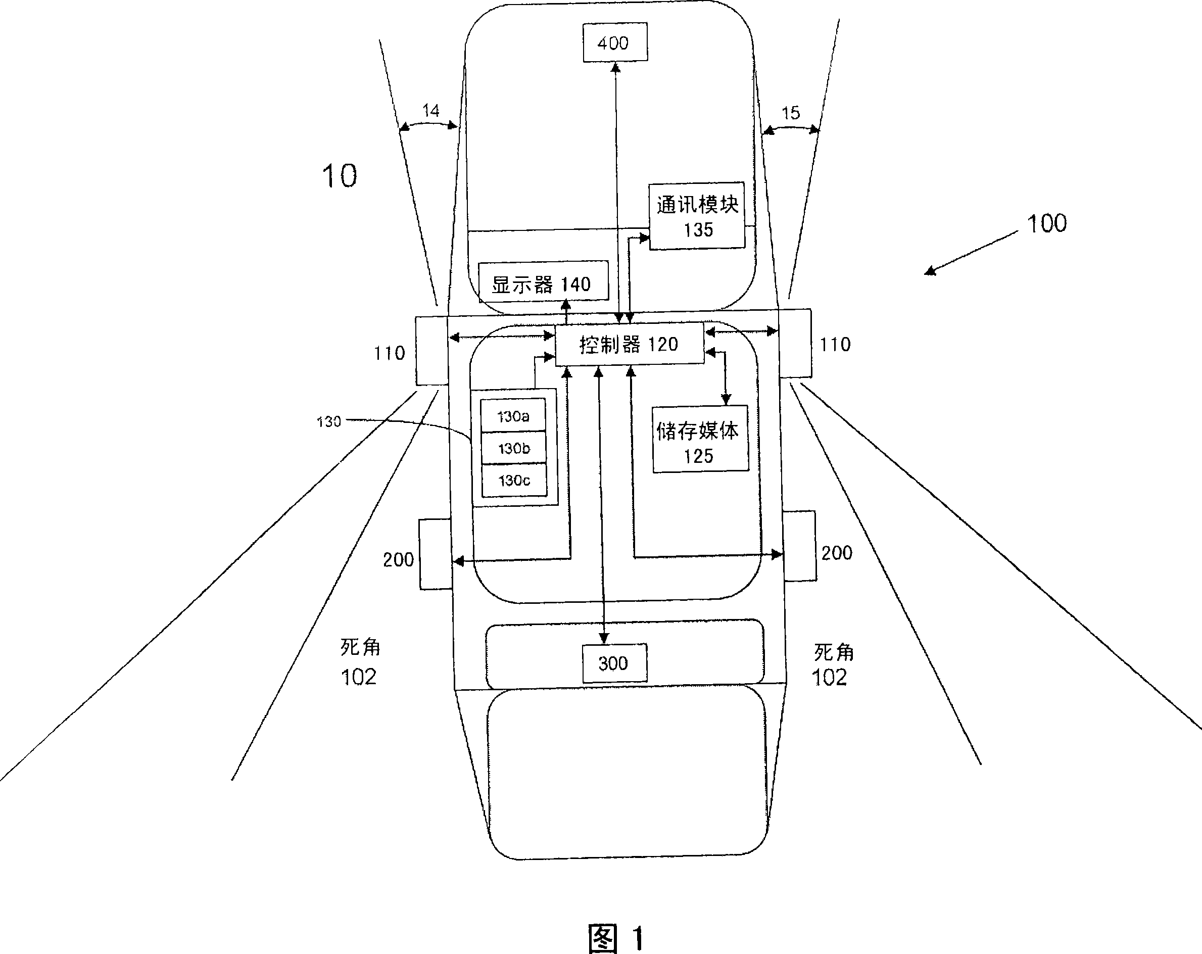
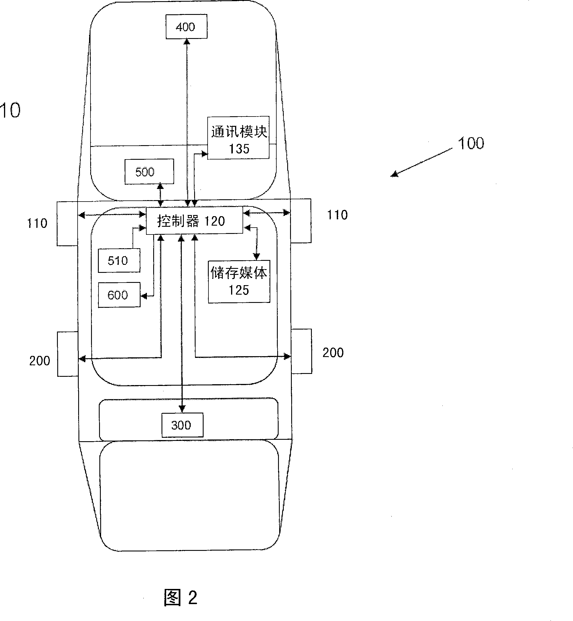
[0031] Referring to FIG. 1 and FIG. 2 , it illustrates that a motor vehicle such as a vehicle 10 includes a status visual monitoring system 100 according to an embodiment of the present invention. An example of the dead space 102 is shown in the figure. For example, the blind spot 102 is an area beyond which conventional exterior rearview mirrors cannot reflect, unless the driver is required to look back. The areas of blind spots 102, 14, 15 may change with the size and position of the mirror and the driver's viewing angle, such as the front and ...


PUM


Abstract

A rear view system for a vehicle comprises a controller; a rear view sensor coupled to the controller and set external of the side panel of the vehicle to capture a rear view image to act the function of external rearview mirror, wherein the controller receives the signal from the rear view sensor; at least one display coupled to the controller to display the rear view image; and storage medium coupled to the controller to store image data. The system further comprises a side view sensor coupled to the controller and set side surface of the vehicle to capture an image within the blind spot of the vehicle, the at least one display coupled to the controller to display the image within the blind spot and the rear view sensor includes a night vision mode.

Description

technical field [0001] The invention relates to a car safety system for automatically displaying the front and rear vision of a car and detecting its adjacent cars, especially a motor vehicle safety system. Background technique [0002] A typical car uses the rearview mirror to monitor the rear view or traffic conditions, and the driver must frequently turn his head to look at the left rearview mirror or the right rearview mirror to confirm the traffic situation. However, there are blind spots that cannot be seen from the driver's position. In addition, moisture and fog on the windshield during rain may reduce visibility and cause traffic accidents. Unfortunately there is currently no effective solution to this problem. Additionally, traffic conditions can change rapidly. Therefore, the driver must frequently wipe off the moisture by hand in this situation, which may be troublesome. At present, there is no effective solution to generate a target detection signal when a t...

Claims


Application Information

Patent Timeline
Patent Type & Authority Applications(China)
IPC IPC(8): G05B19/048G07C5/08G07C5/00
Inventor 江国庆
Owner 江国庆
Why Eureka
Try Eureka