Microwave-accelerated plasmonics

a plasmonic and microwave technology, applied in the field of microwave-accelerated plasmonics, can solve the problems of difficult practical use, limited assays and systems discussed hereinabove, and the plasmons are usually non-radiative, so as to improve the method and system, and increase the kinetics of the reaction system

Active Publication Date: 2012-05-03
UNIV OF MARYLAND BALTIMORE COUNTY
View PDF1 Cites 29 Cited by
  • Summary
  • Abstract
  • Description
  • Claims
  • Application Information

AI Technical Summary

Benefits of technology

[0014]The fact that the plasmon resonance is a sensitive function of nanostructure geometry, coupled with synthetic advances that allow for the controlled and systematic variations in nanostructure geometry, is leading to the expansion of the sensing field called “plasmonics.” The present invention improves on the method and systems using plasmonics by increasing the kinetics of the reaction system and coupling plasmonic emissions induced in metallic structure or essentially continuous film type surfaces with those of the luminescing species.

Problems solved by technology

However, these plasmons are usually non-radiative and difficult to put to practical use.
However, the assays and system discussed hereinabove are limited by the reaction time of the chemical reactions within the assays, such as that which occur in binding or hybridization.

Method used


Image

  • Microwave-accelerated plasmonics
  • Microwave-accelerated plasmonics
  • Microwave-accelerated plasmonics

Examples


example 1

Materials

[0152]Gold nanoparticle dispersions (monodisperse, either 20 or 10 nm average particle diameter), concanavalin A (Con A from Canavalia ensiformis), dextran (average molecular weight: 64000 and 505000) hydrogen peroxide, sulfuric acid, sodium phosphate monobasic, phosphate-buffered saline (PBS), absolute ethanol, 2-(2-aminoethoxy)ethanol (AEE) and N-hydroxy-2,5-pyrrolidinedione (NHS) were obtained from Sigma. 16-Mercaptohexadecanoic acid (16-MHDA) and polyoxyethylene (20) sorbitan monolaurate (Tween 20), epichlorohydrin, 2-methoxyethyl ether (diglyme), and nitric acid were obtained from Aldrich. N-3-(Dimethylaminopropyl)-N′-ethyl-carbodiimide (EDC) was obtained from Fluka. All chemicals were used as received. Buffers and solutions.

[0153]Sodium phosphate monobasic buffer solution was prepared to a 10 mM concentration at pH 7. PBS was dissolved in deionized water and the pH was adjusted to 7.4. Exact pH values for buffer solutions were obtained using a Beckman pH meter. Deioni...

example 2

[0160]This example illustrates a microwave accelerated plasmonics application in which low power microwaves are utilized in solution based plasmon resonance particle assays.

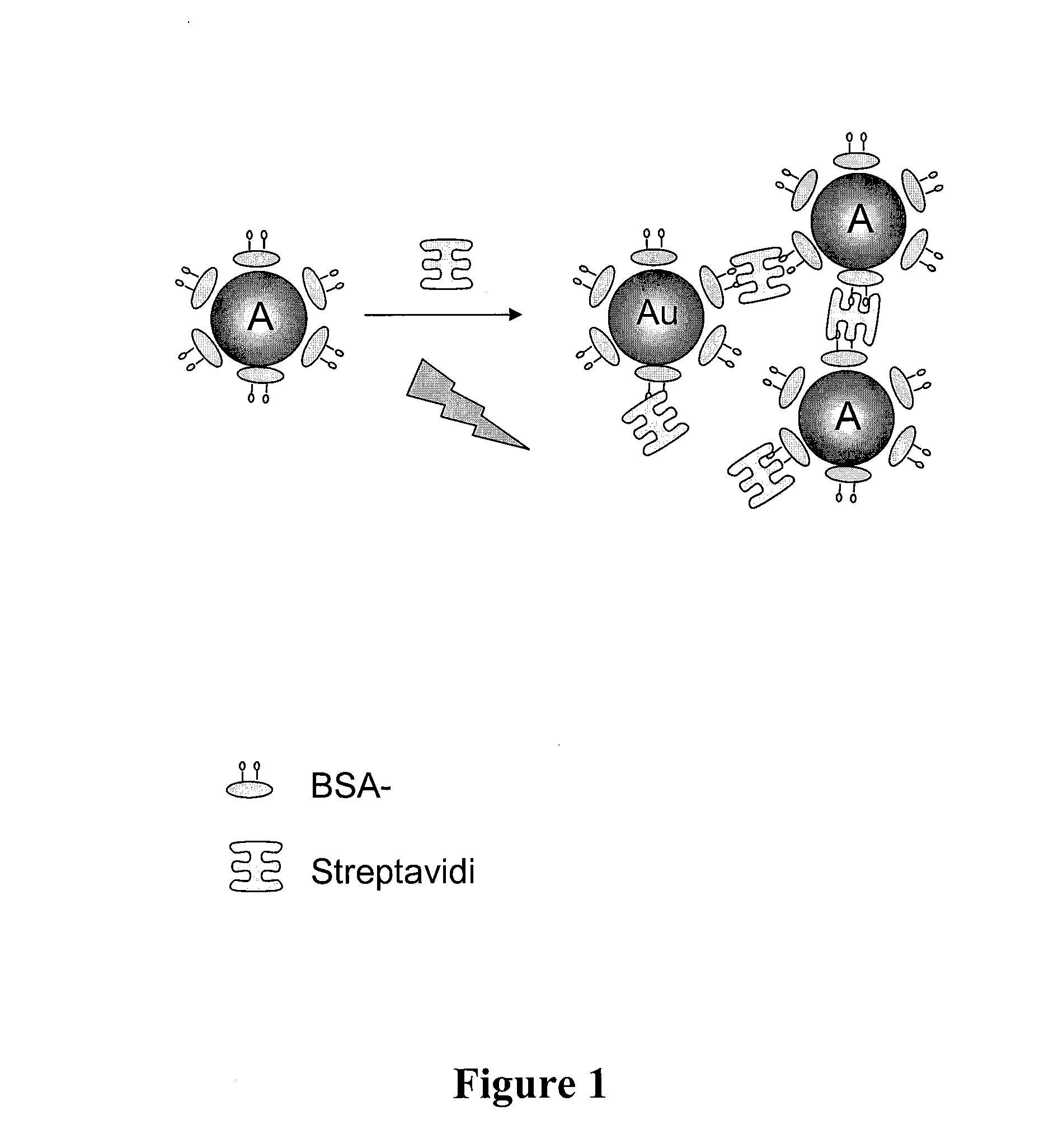
[0161]As a model protein based system, biotinylated-bovine serum albumin coated 20 nm gold particles, crosslinked by additions of streptavidin (a tetravalent protein), are employed. The model system is schematically shown in FIG. 1, in an illustrative depiction of the gold particles (Au) coated with BSA-biotin, undergoing aggregation in the presence of streptavidin and low level microwave energy input.

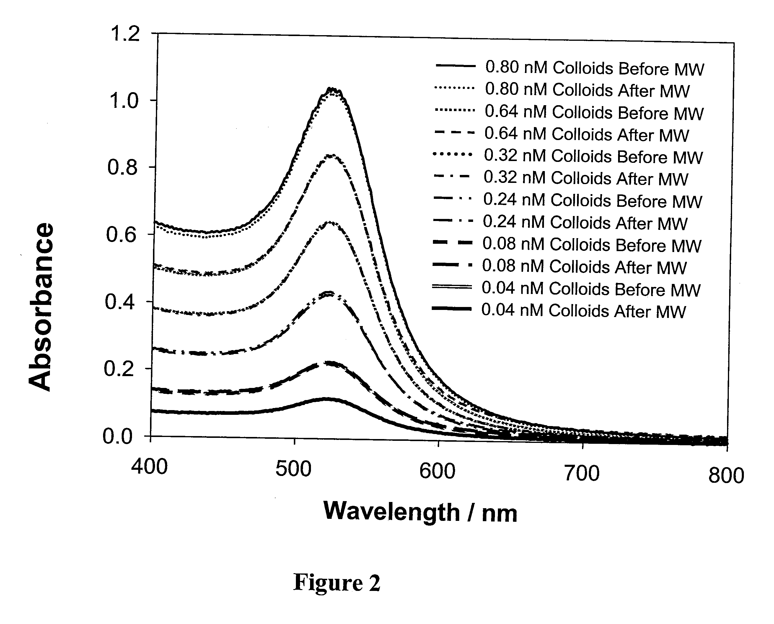
[0162]FIG. 2 shows absorption spectra of 20 nm gold colloids as a function of concentration, before and after exposure to low power microwaves. In FIG. 2, a range of different concentrations of 20 nm gold colloids (0.80 nM; 0.64 nM; 0.32 nM; 0.24 nM; 0.08 nM; and 0.04 nM) can be seen. The plasmon resonances are not perturbed by the low power heating, as shown by the close congruence of the respective curves before a...

example 3

[0177]Bovine-biotinamidocaproyl-labeled Albumin (biotinlyated-BSA) and premium quality plain glass microscope slides (75×25 mm) were obtained from Sigma-Aldrich. Quantum dot 655-labeled streptavidin (Qdots-streptavidin) was obtained from Molecular Probes (Eugene, Oreg.). All chemicals were used as received.

Methods

[0178]Preparation of the Metal Films for Surface Plasmon Coupled Luminescence (SPCL) Spectroscopy

[0179]Firstly, the plain glass slide was coated with a 50 nm thick gold film by vapor deposition (EMF Corp., Ithaca, N.Y.). Then, a tape with a 5 mm circular disk is applied onto the gold film and was lifted-off the surface that resulted in the removal of the gold film except a 5 mm circular disk (FIG. 11). Finally, a black electrical tape that is attached to a self-sticking paper, containing a 5 mm wide circular disk (referred to as a “black body”) was attached on the gold-coated glass slide while the two circular disks matched, prior to the assay fabrication and subsequent SPC...


PUM


Abstract

The present invention relates to systems and methods using microwave accelerated surface plasmonics for the detection of target species, wherein the system has a metallic surface and the system is exposed to microwave energy for increasing detection time and/or the reaction kinetics of the target species and other interacting participants in the system and wherein plasmonic emissions from the metallic surface alone or coupled with emissions from a luminescing entity are detected.

Description

CROSS-REFERENCE TO RELATED APPLICATIONS[0001]The present invention is a Continuation-in-Part application and claims priority of PCT International Application No. PCT / US 2006 / 000029 filed on Jan. 3, 2006 which in turn claims priority to U.S. Provisional Application No. 60 / 641,245 filed on Jan. 3, 2005; and further claims priority to U.S. Provisional Patent Application No. 60 / 788,237 filed on Mar. 31, 2006, and the contents of all priority applications are hereby incorporated by reference herein.GOVERNMENT RIGHTS IN INVENTION[0002]Work related to the invention was conducted in the performance of NIH Grant No. R21 GM 070929-01 and National Center for Research Resources, Grant No. RR008119. As a result of such contracts, the U.S. Government may have certain rights in the invention described herein.BACKGROUND OF THE INVENTION[0003]1. Technical Field[0004]The present invention is directed to a system and method for increasing sensitivity of a detection system, and more particularly, to th...

Claims


Application Information

Patent Timeline
Patent Type & Authority Applications(United States)
IPC IPC(8): G01N21/64B82Y15/00
CPCB82Y15/00B82Y20/00C12Q1/54G01N21/648G01N2021/1731G01N21/78G01N33/54373G01N33/66G01N21/6489
Inventor GEDDES, CHRIS D.ASLAN, KADIR
Owner UNIV OF MARYLAND BALTIMORE COUNTY
Why Eureka
Try Eureka