Shading blind for a roof window of a motor vehicle

a technology for motor vehicles and roof windows, which is applied in the direction of roofs, windows, vehicle components, etc., can solve the problems of reducing assembly effort and saving costs, and achieve the effects of saving costs, increasing headroom of occupants, and less spa

Active Publication Date: 2019-05-09
ROOF SYST GERMANY
View PDF0 Cites 1 Cited by
  • Summary
  • Abstract
  • Description
  • Claims
  • Application Information

AI Technical Summary

Benefits of technology

[0006]The task is solved by the invention of a shading blind of the type mentioned above, in which the receiving space, measured in the direction of adjustment of the roller blind element, has a length which is approximately half of the adjustment distance between the extended and the retracted position, the height of the receiving space, measured perpendicularly to the plane of the roller blind element located between the guide rails, is such that, when the roller blind element is deflected in the receiving space by about 180°, the guide structures are only elastically deformed and a rear edge of the roller blind element is fixed in the receiving space. The extended and retracted position of the roller blind element corresponds to its closed or open position. The basic idea of the invention is to hold the roller blind element “in two layers” in the receiving space (and no longer, as in the state of the art, in several layers wound on top of each other), so that less space is required in the vertical direction. This is made possible by the finding that there is a comparatively large amount of space available in the longitudinal direction which can be used to accommodate the roller blind element without this being detrimental to the occupants of the vehicle. A minimum height of the receiving space results from the elasticity of the flexible guide structures, as these are elastically deformable only up to a certain radius of curvature. For example, the minimum radius of curvature (measured in relation to the center of curvature on the outside of the guide structures) is 7 mm, resulting in a minimum height of 14 mm of the receiving space. Preferably, the height of the receiving space is in the same magnitude as the minimum height, but it can also be greater than the minimum height. In particular, the receiving space is provided in the area of the rear seats of the motor vehicle, which increases the headroom of the occupants in the rear seats. A further advantage of the shading blind according to the invention is that no springs are necessary any more in order to reliably hold the roller blind element in the receiving space when it is moved back to the retracted position. This saves costs and reduces the assembly effort. By fixing the rear edge of the roller blind element, i.e. the edge that is always in the receiving space, there is a pre-defined way in which the roller blind element is “folded” into the receiving area.

Problems solved by technology

This saves costs and reduces the assembly effort.

Method used


Image

  • Shading blind for a roof window of a motor vehicle
  • Shading blind for a roof window of a motor vehicle

Examples


Embodiment Construction

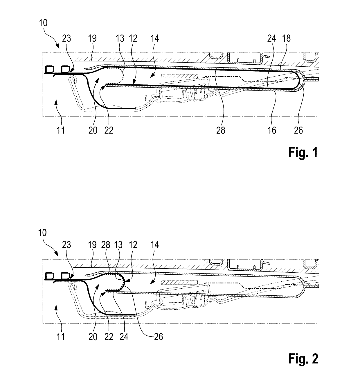
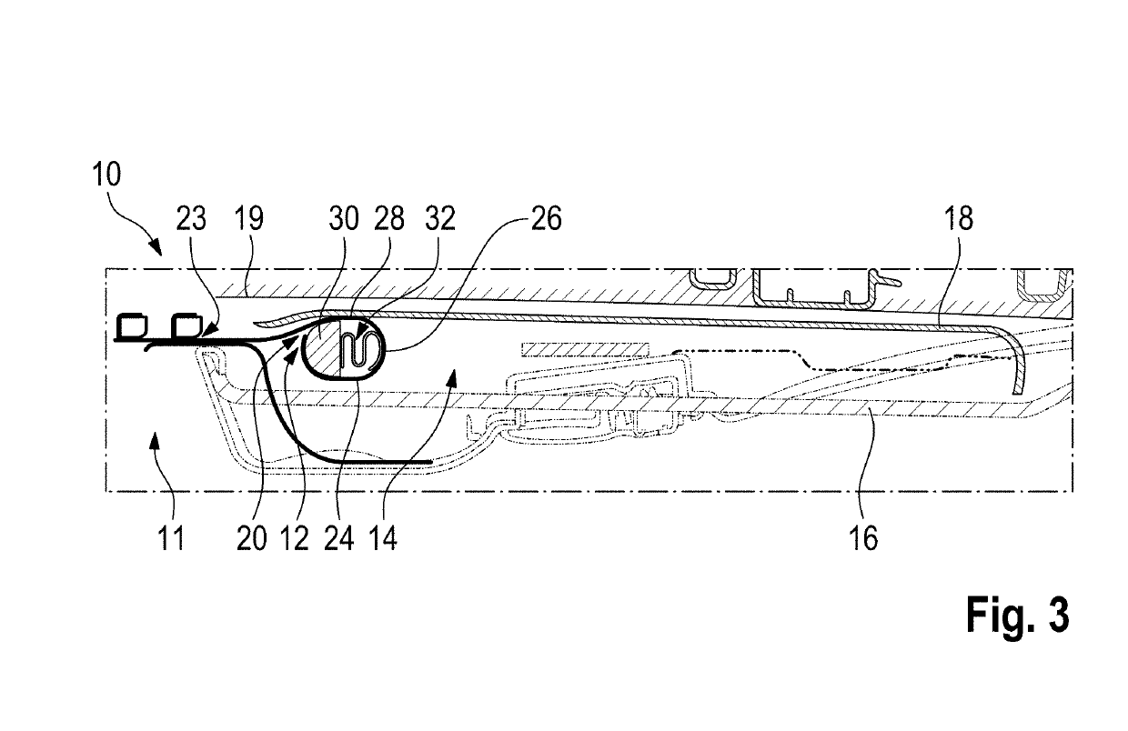
[0021]FIGS. 1 to 3 each show a longitudinal section through a portion of a shading blind 10 as used in roof openings of motor vehicles. The shading blind 10 is used to allow light and / or ambient air to enter at least partially through a roof opening into a vehicle interior 11 or to keep it at least partially away from this interior.

[0022]The shading blind 10 has a roller blind element 12 which is adjustable between a retracted position shown in FIG. 1 and an extended position shown in FIGS. 2 and 3.

[0023]The roller blind element 12 comprises a fabric web with flexible guide structures at its two lateral edges, each of which is, for example, a plastic strip. With these guide structures, the roller blind element 12 is guided in guide rails 13 at least in an area visible from the passenger compartment of the motor vehicle during adjustment between the extended and retracted positions.

[0024]Furthermore, the roller blind element 12 has a front edge (the edge which is visible to an occupa...


PUM


Abstract

A shading blind for a roof window of a motor vehicle is disclosed, having two guide rails, a roller blind element which has two lateral, flexible guide structures with which it is guided in the guide rails, and a receiving space for the roller blind element, the roller blind element being adjustable between an extended position in which it is largely located outside the receiving space, and a retracted position in which it is largely located in the receiving space, wherein the receiving space, measured in the adjustment direction of the roller blind element, has a length which is approximately half of the adjustment path between the extended and the retracted positions, the height of the receiving space, measured perpendicularly to the plane of the roller blind element located between the guide rails, is such that when the roller blind element is deflected in the receiving space by approximately 180°, the guide structures are only elastically deformed and a rear edge of the roller blind element is permanently attached in the receiving space.

Description

CROSS REFERENCE TO RELATED APPLICATIONS[0001]This application claims priority under 35 U.S.C. § 119 to the following German Patent Application No. DE 10 2017 125 721.7, filed on Nov. 3, 2017, the entire contents of which are incorporated herein by reference thereto.BACKGROUND[0002]The invention concerns a shading blind for a roof window of a motor vehicle, comprising two guide rails, a roller blind element having two lateral flexible guide structures with which it is guided in the guide rails, and a receiving space for the roller blind element, the roller blind element being adjustable between an extended position in which it is largely outside the receiving space and a retracted position in which it is largely in the receiving space.[0003]Known shading blinds for roof windows of motor vehicles typically have a shaft on which the roller blind element of the shading blind is wound when it is opened. For this purpose, the roller blind element requires a receiving space which has a rel...

Claims


Application Information

Patent Timeline
Patent Type & Authority Applications(United States)
IPC IPC(8): B60J1/20
CPCB60J1/2086B60J1/2038B60J1/2052B60J1/2033B60J1/2061B60J7/0015
Inventor ROEDER, JOACHIMBECHER, THOMASBIEWER, CHRISTIANADELMANN, FRANZ
Owner ROOF SYST GERMANY
Why Eureka
Try Eureka