

System and method for motor brake boost function failure
a technology of motor brake and function, applied in the direction of braking system, electric device, vehicle sub-unit features, etc., can solve the problems of loss of braking force applied on two tires, the brake system of the vehicle may require extra braking force,
- Summary
- Abstract
- Description
- Claims
- Application Information
AI Technical Summary
Benefits of technology
Problems solved by technology
Method used
Image

Examples
Embodiment Construction
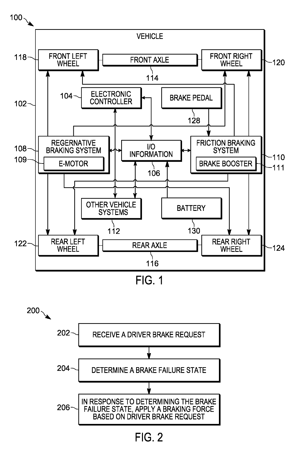
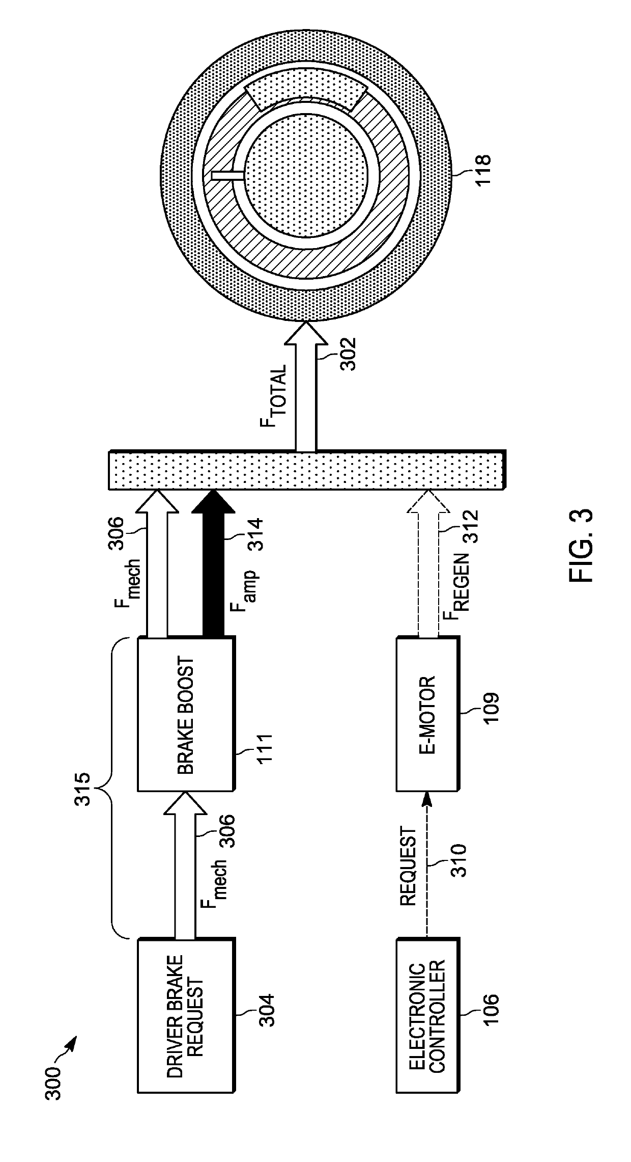
[0011]During a brake system failure, the brake system of the vehicle may require extra braking force in order to stop the vehicle within a certain distance. For example, when the brake booster fails, additional brake force may be required from the driver in order to compensate for the lacking brake force. Less braking force may increase the stopping distance of the vehicle. Some vehicles, for example electric and hybrid vehicles, include regenerative braking systems. Additional braking force may be sourced from the regenerative braking system in order to compensate for the braking force lost due to the brake booster failure.
[0012]One embodiment presented herein includes a braking system. The braking system includes a friction braking system, a regenerative braking system, and an electronic processor. The electronic processor is communicatively coupled to the friction braking system and the regenerative braking system. The electronic processor is configured to receive a driver brake ...
PUM
 Abstract
Description
Claims
Application Information