
Brake control apparatus for vehicle

a technology for controlling apparatus and brakes, which is applied in the direction of braking systems, braking components, transportation and packaging, etc., can solve the problems of reducing the quantity of electrical energy generated by the motor, reducing the efficiency of the braking system, and affecting the abs control effect of the regenerative braking force. achieve the effect of improving energy efficiency

Inactive Publication Date: 2006-10-05
ADVICS CO LTD
View PDF6 Cites 82 Cited by
  • Summary
  • Abstract
  • Description
  • Claims
  • Application Information

AI Technical Summary

Benefits of technology

[0011] The present invention has been accomplished in order to cope with the above-described drawback, and an object of the present invention is to provide a brake control apparatus for a vehicle which performs regeneration-coordinative brake control using frictional braking force, such as hydraulic braking force, and regenerative braking force, as well as ABS control, and which can improve energy efficiency without adversely influencing the ABS control.

Problems solved by technology

In this case, if the regenerative braking force exerted on a wheel which undergoes ABS control during performance of ABS control (hereinafter called a “wheel undergoing ABS control”) is large, in some cases, locking of the wheel undergoing ABS control cannot be properly suppressed through only adjustment of the hydraulic braking force by the ABS control.
In other words, if a regenerative braking force is acting on a wheel undergoing ABS control during performance of ABS control, the regenerative braking force may adversely influence the ABS control.
However, when the regenerative braking force is adjusted to zero, the quantity of electrical energy generated by the motor also becomes zero.

Method used


Image

  • Brake control apparatus for vehicle
  • Brake control apparatus for vehicle
  • Brake control apparatus for vehicle

Examples


Embodiment Construction

[0055] A brake apparatus (brake control apparatus) for a vehicle according to an embodiment of the present invention will be described with reference to the drawings.

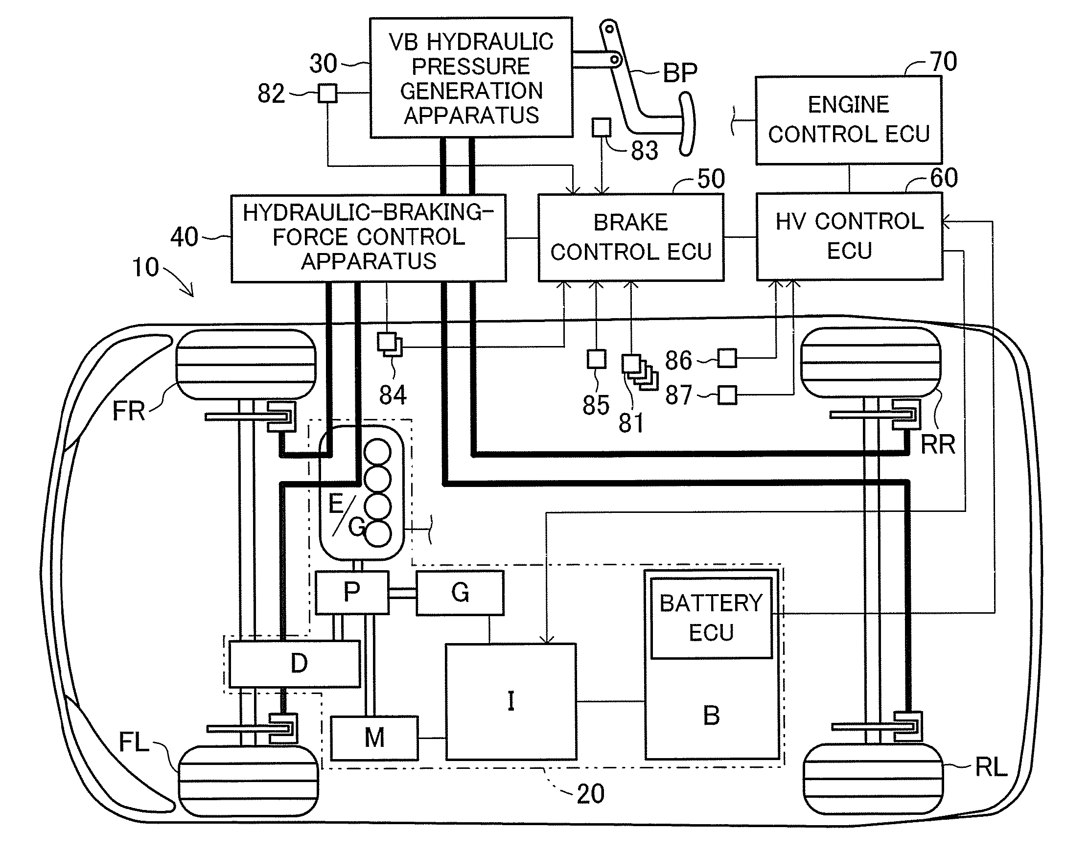
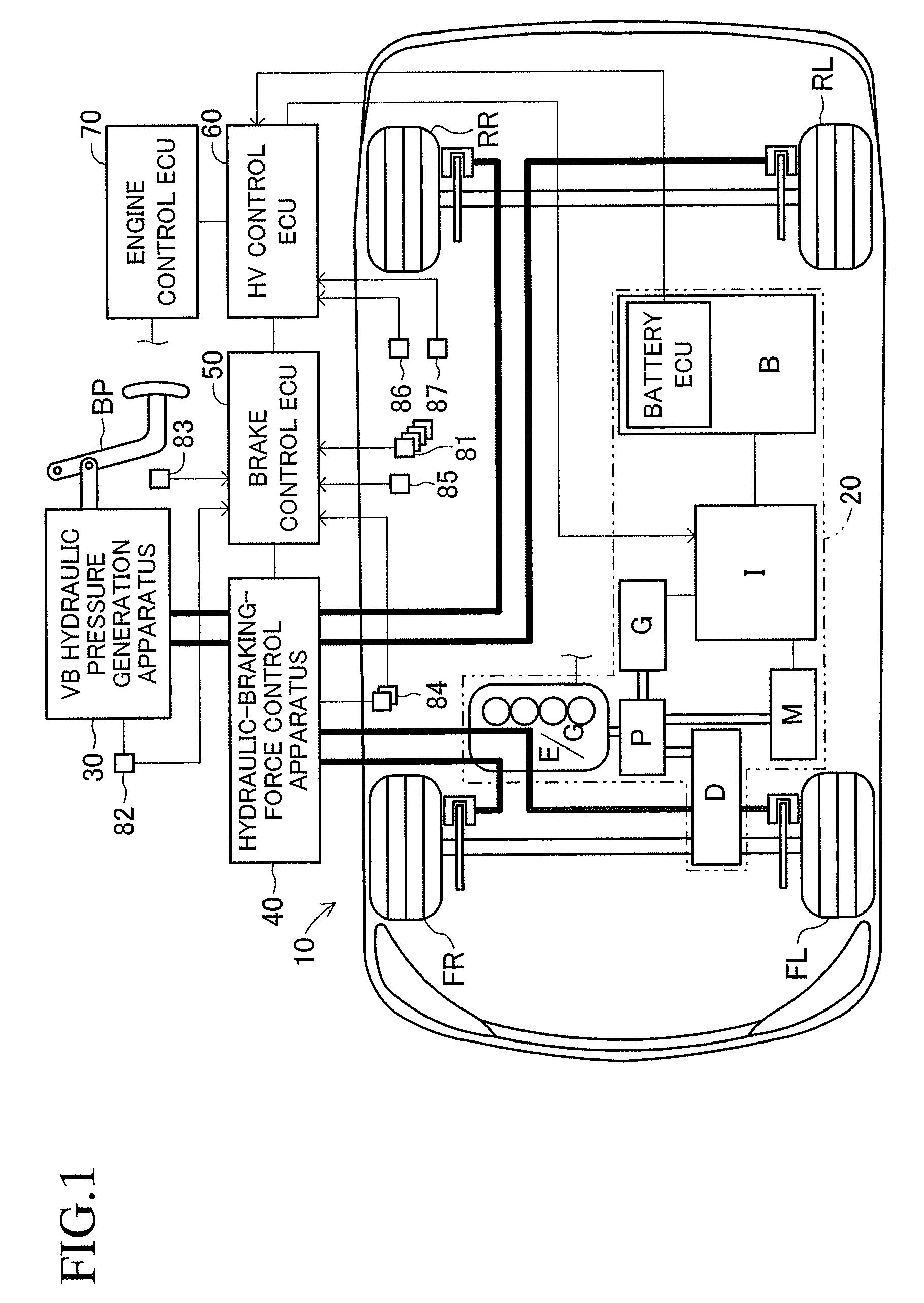
[0056]FIG. 1 schematically shows the structure of a vehicle equipped with a brake apparatus 10 according to the embodiment of the present invention. The illustrated vehicle is a so-called hybrid vehicle of a front-wheel drive type which uses an engine and a motor as a drive source for driving the front wheels and which includes two brake hydraulic circuits (that is, front-rear piping system); i.e., a system for the two front wheels and a system for the two rear wheels. The two front wheels correspond to “specific wheels.”

[0057] This brake apparatus 10 includes a hybrid system 20 having two types of power sources; i.e., an engine E / G and a motor M; a vacuum-booster hydraulic pressure generation apparatus (hereinafter called the “VB hydraulic pressure generation apparatus”) 30 which generates brake hydraulic pressure in ...


PUM


Abstract

A brake apparatus for a vehicle controls braking force acting on front wheels by hydraulic braking force (front-wheel-side vacuum-booster hydraulic pressure fraction+linear-valve differential pressure fraction), which is frictional braking force, and regenerative braking force, and controls braking force acting on rear wheels by hydraulic braking force (rear-wheel-side vacuum-booster hydraulic pressure fraction) only, to thereby perform regeneration-coordinative brake control. During performance of ABS control, the apparatus sets the limit regenerative braking force to a force under which locking of the front wheels does not occur in a case in which the force acts on the front wheels, which are wheels undergoing regenerative braking, and adjusts the regenerative braking force such that the regenerative braking force does not exceed the limit regenerative braking force.

Description

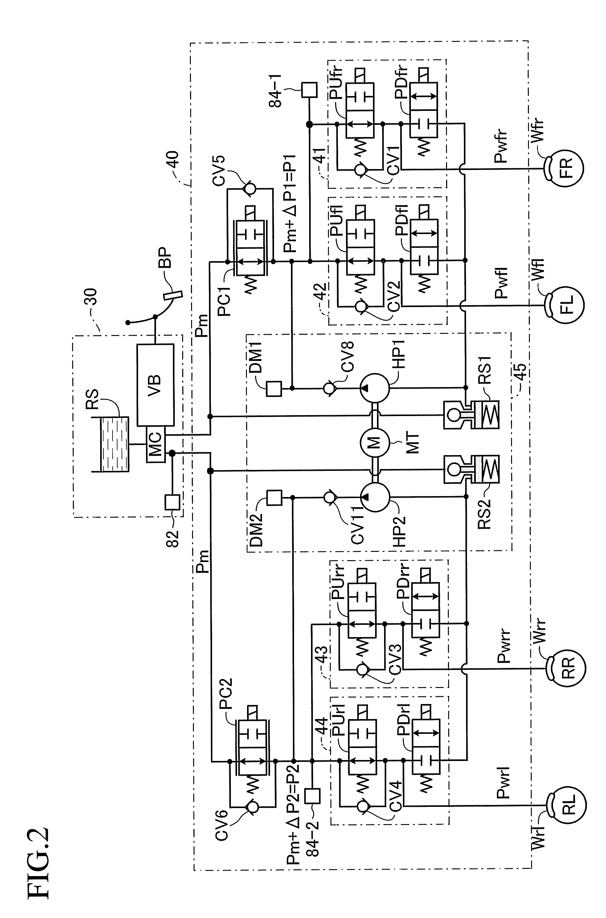
BACKGROUND OF THE INVENTION [0001] 1. Field of the Invention [0002] The present invention relates to a brake control apparatus for a vehicle. [0003] 2. Description of the Related Art [0004] Recently, there has been developed a brake control technique which is applied to a motor-driven vehicle using a motor as a power source or a so-called hybrid vehicle using a motor and an internal combustion engine as a power source and which performs regeneration-coordinative brake control using braking force on the basis of hydraulic pressure (hydraulic braking force) as well as regenerative braking force generated by the motor. [0005] More specifically, a brake apparatus for a vehicle which performs the above-described regeneration-coordinative brake control is generally designed to adjust the hydraulic braking force and the regenerative braking force in accordance with a force with which a brake pedal is operated (brake pedal depressing force) such that the characteristic of total braking forc...

Claims


Application Information

Patent Timeline
IPC IPC(8): B60T8/64B60L7/24B60T8/17B60W10/184
CPCB60L7/26B60L2210/20B60T1/10Y02T10/725B60W10/08B60W10/184B60W30/18127B60T2270/602Y02T10/72
Inventor SAITO, SHIGERUMATSUURA, MASAHIROKOKUBO, KOICHISENGOKU, YUJI
Owner ADVICS CO LTD
Learn More