
Anti-vibration thread form

a technology of anti-vibration threads and threaded fasteners, which is applied in the direction of threaded fasteners, screws, fastening means, etc., can solve the problems of loosing under vibration, requiring additional material costs and application costs, and limited options for providing vibration resistance internally threaded fasteners, etc., to achieve the effect of improving the vibration resistance of threaded fasteners

Active Publication Date: 2019-05-09
INFASTECH INTPROP PTE
View PDF10 Cites 0 Cited by
  • Summary
  • Abstract
  • Description
  • Claims
  • Application Information

AI Technical Summary

Benefits of technology

This patent aims to improve the vibration resistance of threaded fasteners by developing new thread profiles that provide point contact. These new profiles allow the fastener to spin freely while mating and be reused multiple times, eliminating the need for alternative vibration mitigation techniques. The technical effects of this patent text are improved vibration resistance and enhanced reusability of threaded fasteners.

Problems solved by technology

A common problem with prior fasteners included loosening under vibration.
Due to the high pressures and large diameters, the available options for providing vibration resistant internally threaded fasteners has been limited.
However, thread coatings require additional material cost and application cost, and the amount of material increases significantly as fasteners become larger.
Some applications have relied upon excessive force to force a nut onto a threaded connection, which may result in deformation preventing reuse of the nut once it is removed.
Still other approaches have required modifications that prevented the threaded connection from being easily rotated thereby increasing the difficulty of using such devices.

Method used


Image

  • Anti-vibration thread form
  • Anti-vibration thread form
  • Anti-vibration thread form

Examples


Embodiment Construction

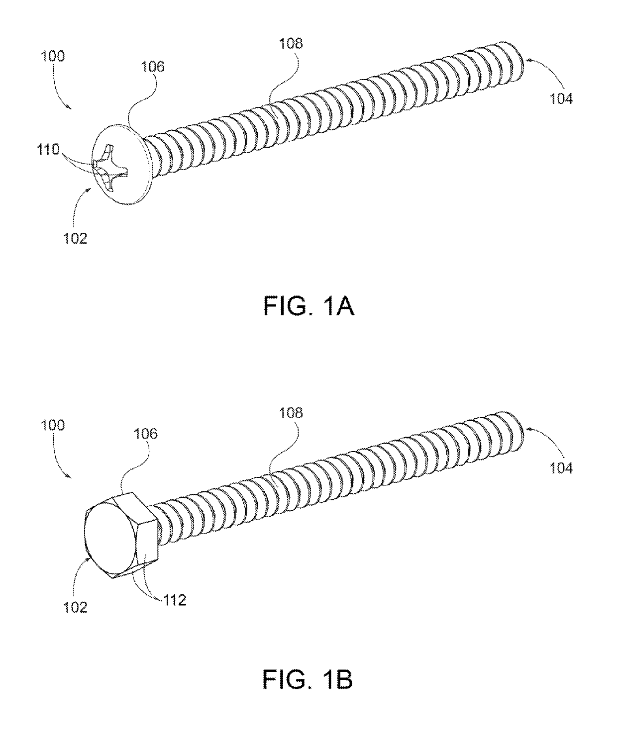
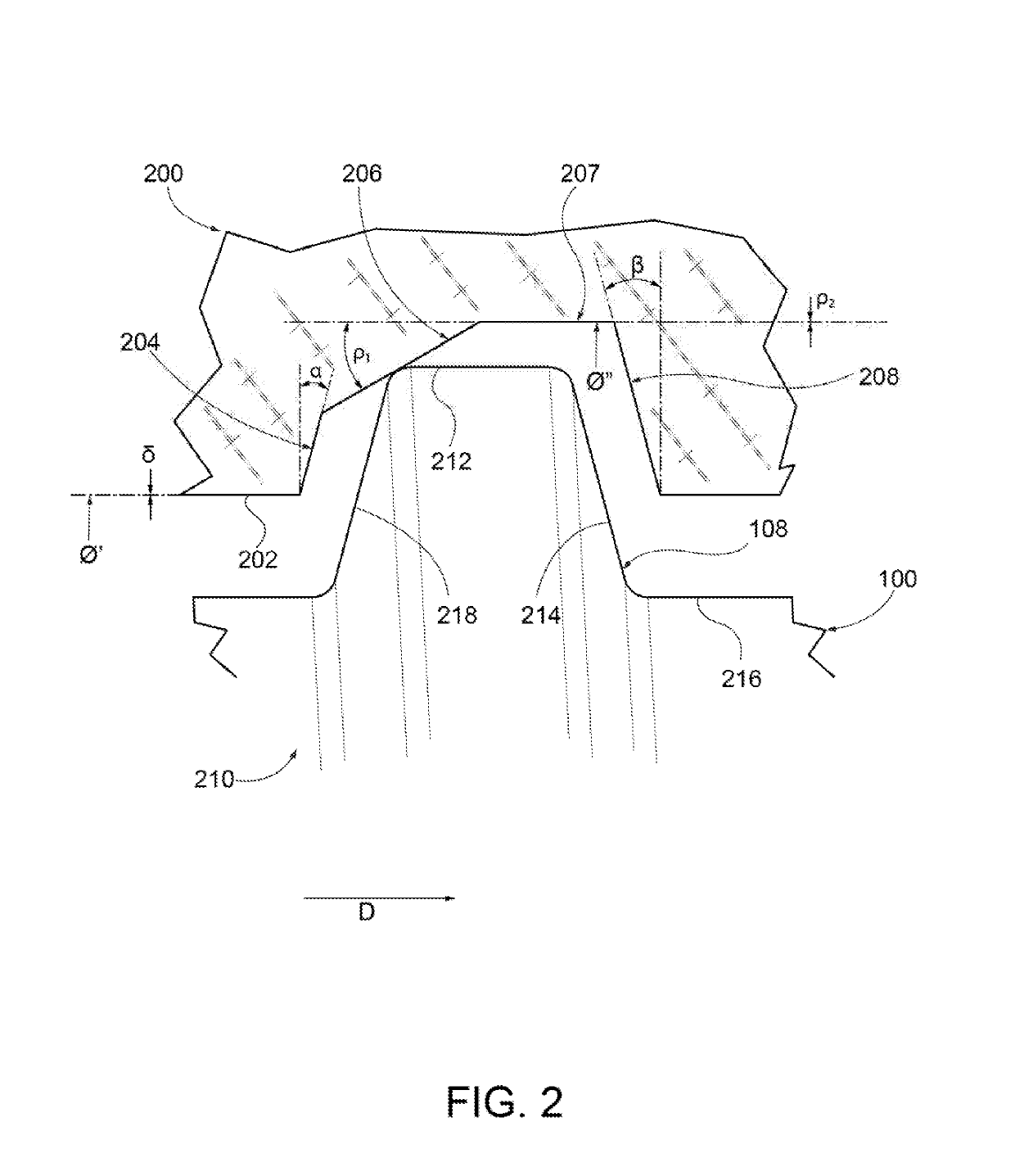
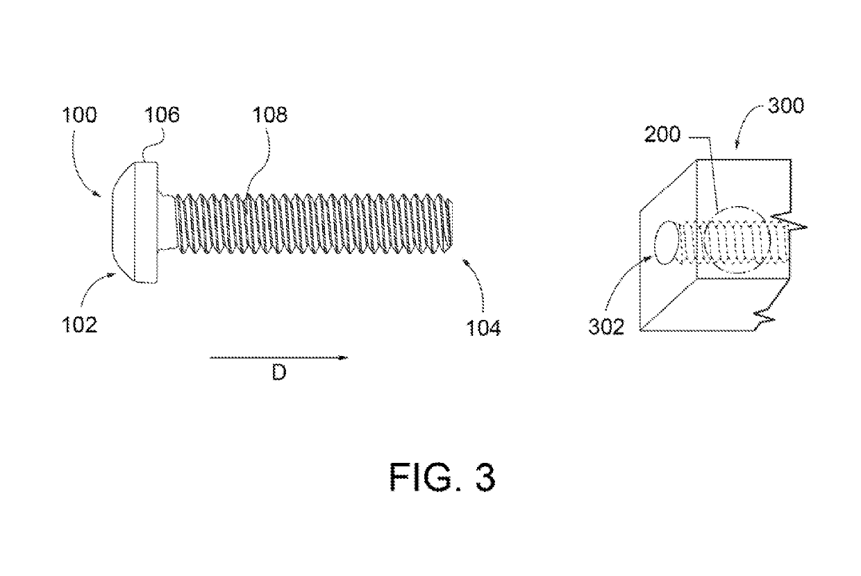
[0020]Referring now to FIGS. 1-4, embodiments of the presently disclosed threaded fastener and fastener system are illustrated. As shown in FIG. 1A and FIG. 1B, an externally threaded fastener 100 includes a threaded portion 108 extending from a first end 102 to a second end 104. The second end 104 may alternatively be referred to as the lead end of the fastener based upon the driving direction D of the fastener. In one embodiment, the threaded fastener is a screw having a head 106. The threaded portion 108 is defined by a helical thread extending around an elongated shank that extends from the head 106 to the second end 104. As described further below, the thread is defined by at least a crest portion, a leading flank, a root portion, and a trailing flank. The configuration of the thread may be defined by reference to a longitudinal axis and / or a normal axis of the threaded fastener. The longitudinal axis extends through the fastener from the first end to the second end, whereas th...


PUM


Abstract

A threaded fastener having a thread defined by a crest portion, a leading flank, a first root portion, a second root portion, and a trailing flank, configured to engage an externally threaded trapezoidal threadform. The thread may alternatively be defined by a foot portion, a leading flank, a first crest portion, a second crest portion, and a trailing flank, configured to engage an internally threaded trapezoidal threadform.

Description

CROSS-REFERENCE TO RELATED APPLICATION[0001]This application claims priority to U.S. Provisional Patent Application No. 62 / 329,673, filed Apr. 29, 2016, the disclosure of which is incorporated herein by reference.BACKGROUND AND SUMMARY[0002]The present invention relates generally to threaded fasteners of any size, and more particularly to vibration resistant, internally threaded fasteners for use with trapezoidal thread forms.[0003]Threaded fasteners having trapezoidal thread forms are used in many applications, and especially in applications where the fastener will be subjected to large forces, such as fire hydrants and drive screws. Many applications of these applications require that threaded fasteners maintain desired clamping forces through vibration and other in-use loads. A common problem with prior fasteners included loosening under vibration. These applications also frequently use larger diameter fasteners, such as those with a major diameter of at least two inches. In addi...

Claims


Application Information

Patent Timeline
IPC IPC(8): F16B33/02
CPCF16B33/02F16B39/30
Inventor BOSTICK, RYANPEACOCK, KEVIN
Owner INFASTECH INTPROP PTE
Learn More